Tension control system for a continuous winding machine

a technology of continuous winding machine and control mechanism, which is applied in the direction of rolling mill control device, manufacturing tools, transportation and packaging, etc., can solve the problems of inability to meet the requirements of coil construction, inability to use common feed rate control techniques, and variable filament tension, etc., to achieve winding to tolerances and easy handling of thin filaments

Inactive Publication Date: 2011-02-22
HENSON TECH LLC
View PDF14 Cites 21 Cited by
  • Summary
  • Abstract
  • Description
  • Claims
  • Application Information

AI Technical Summary

Benefits of technology

An advantage of the present invention is that the machine can wind to tolerances much tighter than those of current art machines.
Another advantage of the present invention is that the wind angle can be controlled to vary the preload, or stiffness, of the coil product.
Yet another advantage of the present invention is that it can more easily handle thin filaments.
A still further advantage of the present invention is that the programming control can be accomplished by remote access means.
Still another advantage of the present invention is that the machine provides automatic counterbalancing of the winding module.

Problems solved by technology

The very small diameters of the elements involved and the tight tolerances required make it difficult for current art equipment to construct the coils to the required specifications and without breakage.
One disadvantage of the prior art devices is that they typically use only one-way feed friction control, which produces filament tension that varies with feed rate.
While this methodology is acceptable for applications using relatively large filament sizes, for the smaller filament sizes required in, for example, current art medical devices, the forces involved in commonly used feed rate control techniques are not acceptable The force necessary to control the feed rate is greater than the filament can withstand, so that breakage occurs.
Another disadvantage of the prior art devices is that the non-distributed control systems are too large and require too many control wires to enable an independent filament dispenser to spin around a mandrel, as continuous winding requires.
A further disadvantage of prior art systems that use control systems separate from the filament dispensing control is that multiple slip rings are required to operate with the supply spools rotating around the mandrel.
The slip rings wear out quickly, and create debris that is unacceptable in cleanroom environments.

Method used


Image

  • Tension control system for a continuous winding machine
  • Tension control system for a continuous winding machine
  • Tension control system for a continuous winding machine

Examples


Embodiment Construction

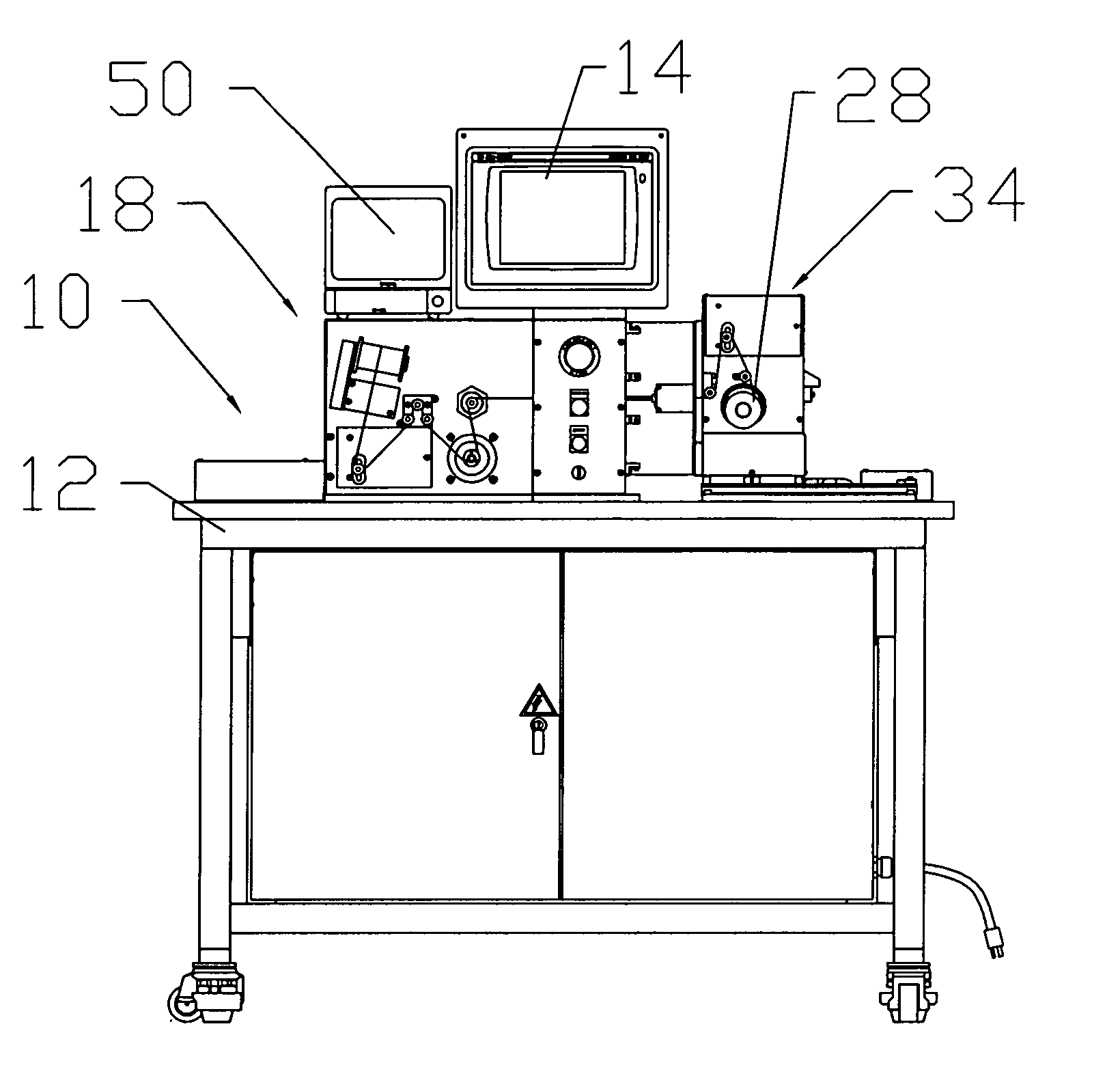
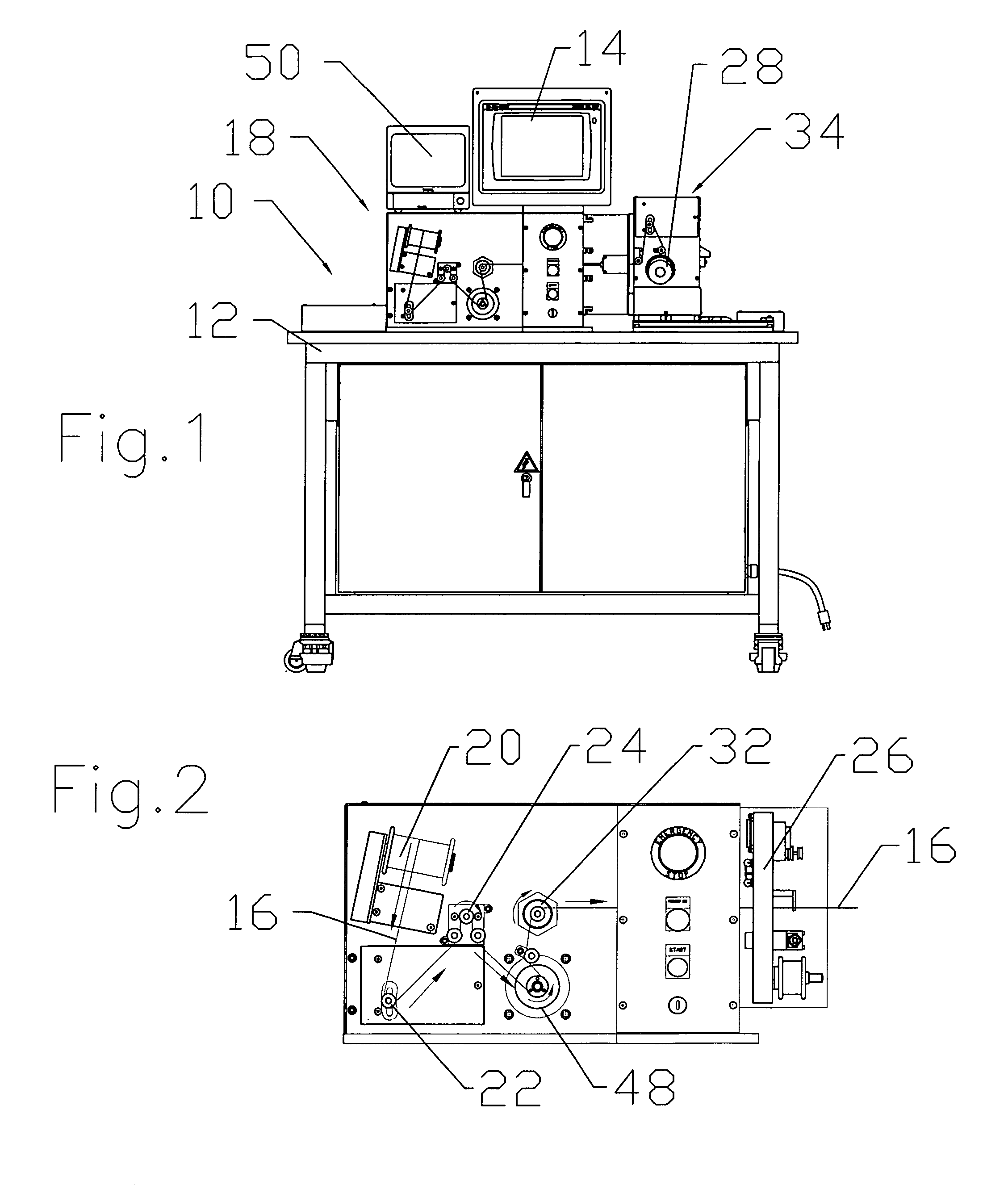
The present invention is a continuous winding machine 10. The mechanical structure of the winding machine 10 can best be understood with reference to FIGS. 1-6. The winding machine 10 is installed on a movable mounting table 12. A touchscreen 14 enables the user to easily program the various operations performed by the machine 10 by choosing a pre-installed manufacturing recipe, and / or creating modified recipe settings.

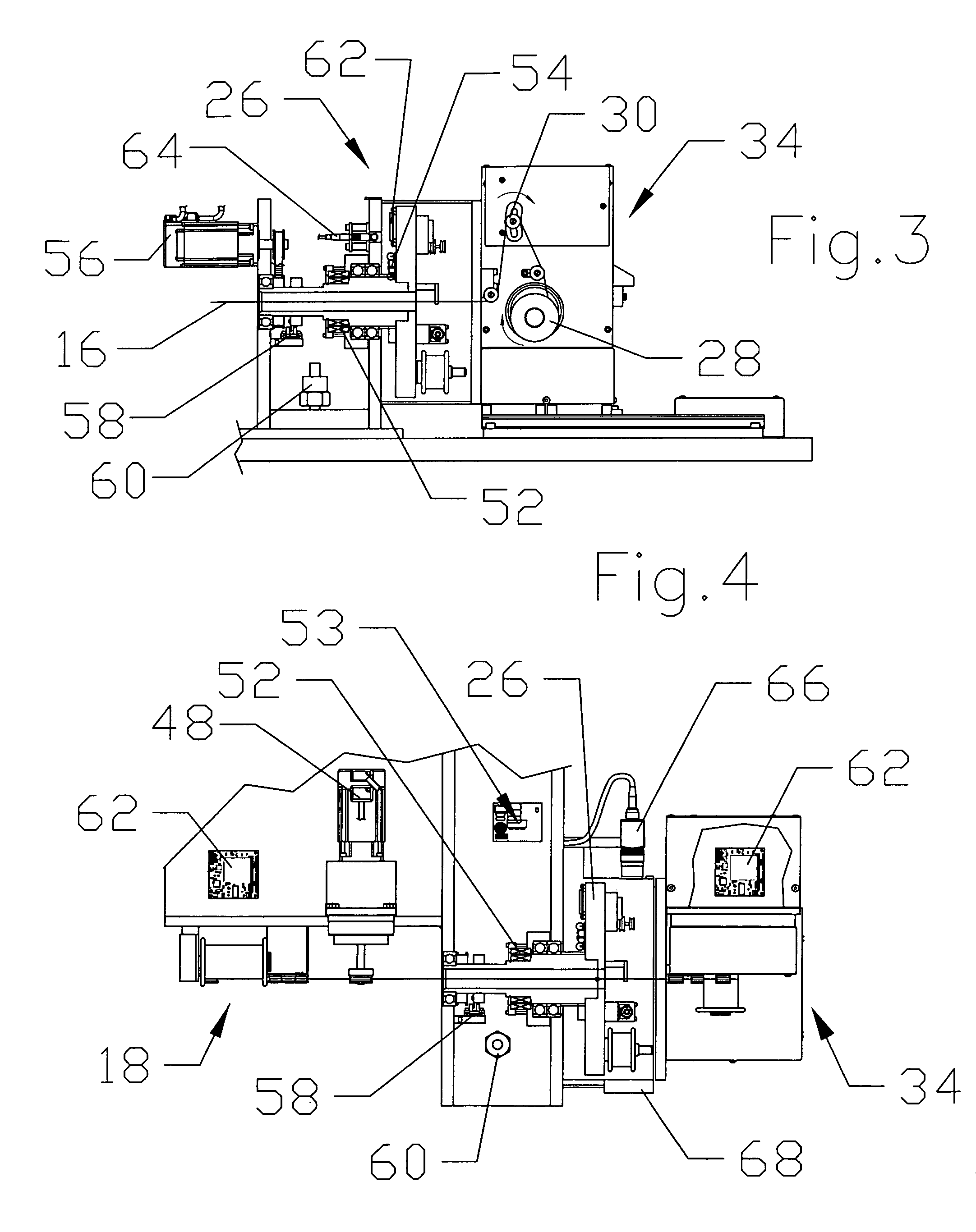
The central element of the product being manufactured by the winding operation is a mandrel 16, the core of the wound product. The mandrel 16 is fed into the winding machine 10 from a mandrel supply assembly 18. The mandrel 16 is fed off a mandrel supply spool 20, across a first dancer 22, and then across a first load cell 24 around the pitch drive 48 and over a second load cell 32 associated with a mandrel takeup spool 28.

The mandrel 16 is then fed into the cylindrical housing of the winding module 26. After the mandrel 16 has passed through the winding module 26, th...


PUM

PropertyMeasurementUnit
angleaaaaaaaaaa
tensionaaaaaaaaaa
Winding Speedaaaaaaaaaa

Abstract

A continuous winding machine uses embedded controllers to monitor and control the winding settings in maximum speed applications. Power is supplied to the embedded controllers from a main power source through a rotary transformer. The control system can be operated either through wired connections to a local computer or processor, or through a wireless system, or a combination of both, depending on the specific application. The machine uses a high speed, closed loop tensioning system that includes the filament supply spools and the mandrel supply and takeup spools. The control system menu includes the various winding operations useful to each user. The control system menu can be accessed remotely via computer, or by telephone.

Description

BACKGROUND OF THE INVENTION1. Field of the InventionThe present invention relates generally to tension control systems, and more particularly is an improved tension control mechanism for a continuous winding machine that utilizes wireless or wired embedded closed loop feedback systems.2. Description of the Prior ArtCoil winding technology has existed for quite some time in various fields. For example, the textile industry has long used winding methods to spool threads and yarns. Some examples of references in this area are the “Method and Apparatus for Winding a Thread on a Bobbin at a High Winding Speed” by Hori, et al., U.S. Pat. No. 4,059,239, issued Nov. 22, 1977; “Winding Apparatus” by Davies, U.S. Pat. No. 4,538,772, issued Sep. 3, 1985; and the “Operation Controlling Method for Textile Machine” of Matsui, et al., U.S. Pat. No. 4,984,789, issued Jan. 15, 1991. Another large subset of winding machines is directed to the art of coil winding for electric motor armatures. See, e.g...

Claims


Application Information

Patent Timeline
Patent Type & Authority Patents(United States)
IPC IPC(8): B65H54/64B21B39/08
CPCB65H59/12B65H59/40B65H63/006
Inventor HENSON, DALE L.
Owner HENSON TECH LLC
Why Eureka
Try Eureka