Tandem ion-trap time-of-flight mass spectrometer

a mass spectrometer and time-of-flight technology, applied in mass spectrometers, isotope separation, particle separator tubes, etc., can solve the problems of inability to teach how to achieve this in practice, inability to efficiently eliminate the turn-around time, and hardly possible optimisation, so as to improve the quality of tof mass analysis such as resolution and mass accuracy, and improve performance.

Inactive Publication Date: 2011-03-01
SHIMADZU RES LAB EURO
View PDF31 Cites 29 Cited by
  • Summary
  • Abstract
  • Description
  • Claims
  • Application Information

AI Technical Summary

Benefits of technology

[0011]The present inventors have realised, that the combination of a digital ion trap with TOF provides a tandem mass spectrometer with improved performance. The quality of TOF mass analysis such as resolution and mass accuracy can be improved by optimising conditions of ion ejection into TOF, which is only possible if fields are constant during the ejection process. In order to achieve such conditions authors propose to use the ion trap with digital drive, so that the voltages within the trap remain constant with high precision on application of extraction pulses. Thus the extraction voltages and switching time can be optimised in such way, that ion cloud leaves the ion trap having optimum phase-space distribution for further processing. Further processing can include mass analysis using TOF, or post acceleration stage of TOF mass spectrometer, or it can be any other ion optical device that requires pulses of ions. In each case the distribution of ion positions and velocities can be optimised for each particular purpose. After ejecting of ions out of the trap the trapping waveform is returned to original state allowing the next cycle of ion introduction, manipulation and mass analysis.
[0012]In preferred embodiments the invention includes an ion source with transmission ion optics including storing and pulsing ion guide, a linear ion trap filled with neutral gas of mTorr or higher pressure and a time-of-flight analyser. Ion trap is driven by a digital switches connected to all four main electrodes in order to provide periodic trapping potential consisting of at least 2 discreet DC levels. A square wave with equal positive and negative DC levels is preferable as the most simple trapping waveform allowing to trap a wide mass range of ions. Ions from the ion source are transmitted into a linear ion trap and injected into the trapping volume from a region of low field near the central axis of the trap. Ions are manipulated within the trap in a desired manner. These manipulations can include several stages of cooling, isolation of selected ion species by removing all ions with other mass-to-charge ratio and fragmentation of ions by using any of methods known in the art such as collisionally induced dissociation (CID), surface induced dissociation (SID), electron assisted dissociation, photon induced dissociation or other. Finally, remaining ions are cooled down by collisions with light buffer gas and collected near the central axis of the trap in a cigar-like cloud. At appropriate time the period of the trapping square wave is changed to a longer value and the extraction pulse is applied shortly after that. At least one of the electrodes of a linear ion trap has a slit through which the ions are ejected out of the trap. Digital signal generator (DSG) allows controlling the actual voltage state on the electrodes of the trap before the period change applies (switching state). The switching state, the duration between the start of last state and the start of the extraction pulse (duration of the last state prior to ejection) is adjusted in such way as to produce the best distribution of ions for further processing in TOF mass analyser. In preferred embodiments the TOF has a flight path orthogonal to the axis of linear ion trap and equipped with an ion mirror (reflectron).
[0013]In the first preferred embodiment the ions are ejected out of the trap into a pulsar, which is located parallel to the axis of ion trap and orthogonal to the TOF axis. On arrival of ions into the pulsar a high voltage pulse is applied to the electrodes of the pulsar in order to accelerate ions into the ion path of TOF. Acceleration voltages in the pulsar are as big as possible in order to reduce the turn-around time of ions. Ions are reversed in the TOF by an ion mirror and focused to the detector in such way that ions of the same mass-to-charge ratio arrive as close to each other in time as possible. A wide multi channel plate can be used as a detector. Arriving at the detector ions produce electrical pulses in the circuit, which are registered by a recording system. A digitiser with high sampling speed (1 Gsample / s or over) and high dynamic range (12 bit or over) is preferable.
[0015]In yet another preferred embodiment the trapping of ions is achieved by driving only one set of the rods of the linear ion trap (Y electrodes) by switching between positive and negative DC levels. The high voltage switches for extraction are connected to another pair of rods (X electrodes) at least one of which has a slit for ejecting ions towards TOF. This kind of power supply is referred as “two-pole” digital trapping waveform. An advantage of this configuration is the possibility of separating the high voltage and trapping voltage supply from each other, which simplifies electronics and reduces the overall cost of instrument. As a result of such separation, the digital driving waveform on Y electrodes is not switched off during ejection. Only the switching period is changed to a longer value allowing all ions to be ejected from the trap with assistance of high voltage pulse.

Problems solved by technology

The method described in this patent uses comparatively low extraction voltages (below 500V) and hence does not allow efficient eliminating of the turn-around time.
Both patents suggest that RF is not present during ejection process, but do not teach how this can be done in practice.
It is obvious that such optimisation is hardly possible if sinusoidal RF inside the trap is still running during the ejection process.
It is known that a typical 3D trap can hold up to 107 ions, but high resolution manipulations with ions by using supplementary AC signals is only possible if the total amount of elementary charges inside 3D trap is below few thousands.
Such throughput is not acceptable for most applications as modern ion sources can provide total ion current of several nA.
In general the method suffers from mass discrimination of ions.
As a result, such instrument has low throughput.
The patent does not teach how to switch off the RF field although it is mentioned as a difficult practical problem.

Method used


Image

  • Tandem ion-trap time-of-flight mass spectrometer
  • Tandem ion-trap time-of-flight mass spectrometer
  • Tandem ion-trap time-of-flight mass spectrometer

Examples


Embodiment Construction

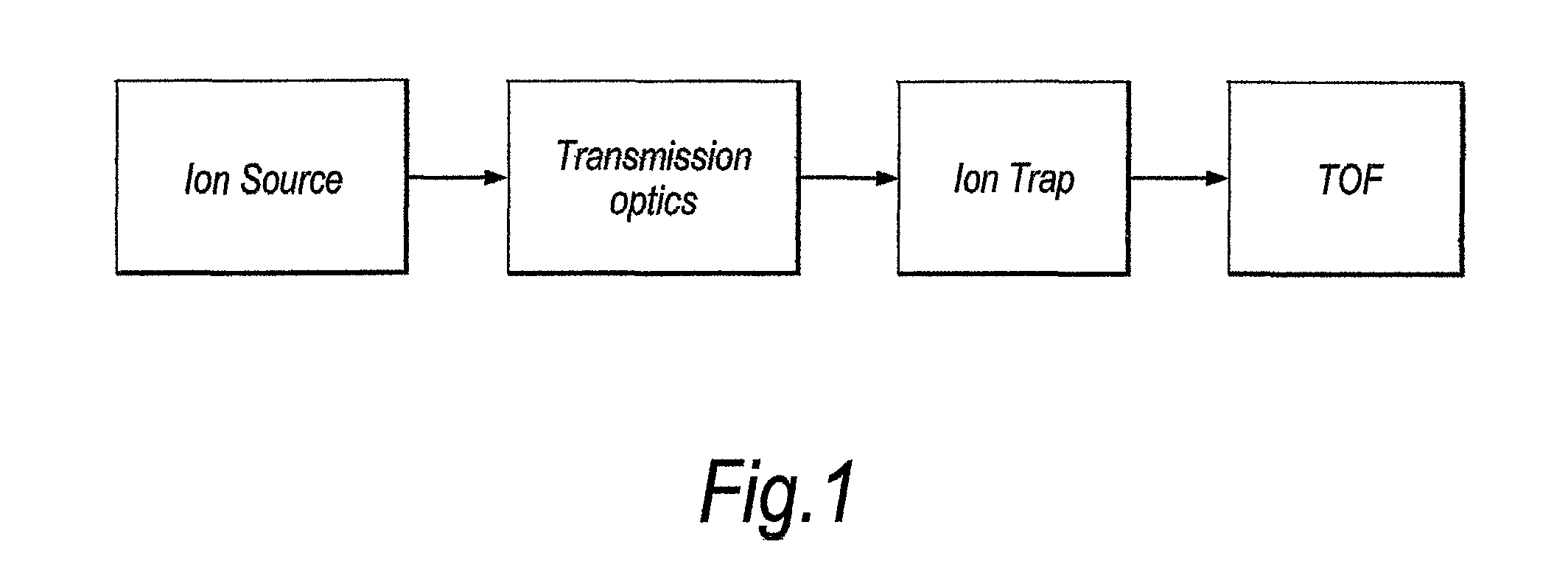
[0035]Referring to FIG. 1 there is a block diagram of a tandem IT-TOF mass spectrometer including the ion source, means to transmit ions into the ion trap and time-of-flight mass spectrometer. The ion source is positioned external to the ion trap. Ions can be generated in the ion source by any of the methods known in the art. In particular the electrospray ion source and MALDI are most commonly used for ionisation of molecules of biological nature. Ion source can operate at elevated pressure and ions are collected from ion source and transmitted through regions of differential pumping into the ion trap with the help of RF ion guides. Ions are manipulated inside the trap and prepared for mass analysis using TOF.

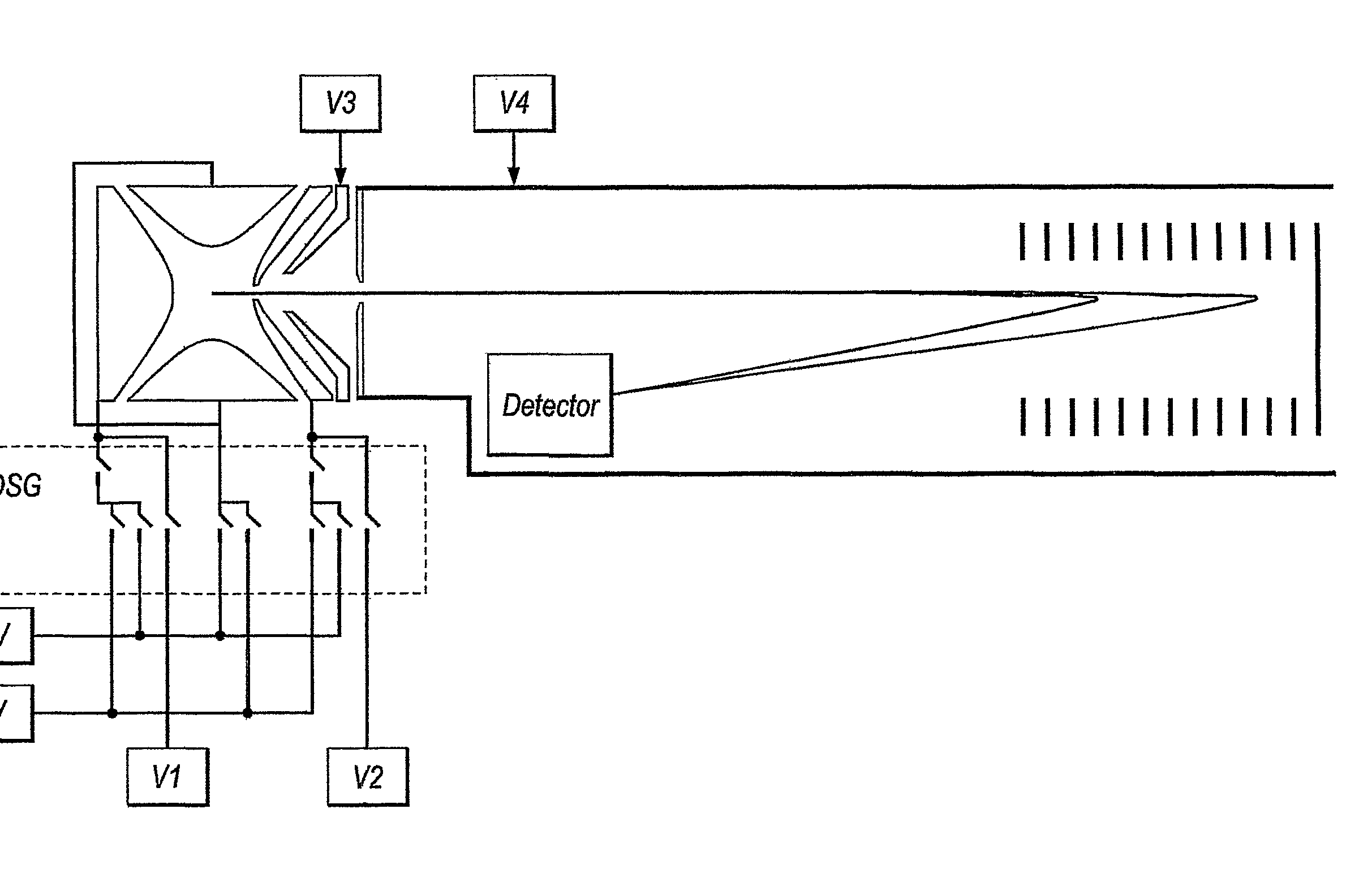
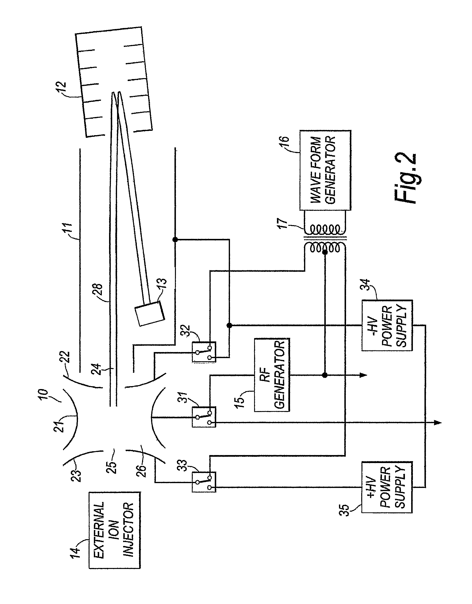
[0036]IT-TOF tandem can be built on the basis of 3D trap. Configuration of such instrument with ejection of ions out of the trap directly into the TOF flight path is presented on FIG. 2. However, such configuration suffers from low introduction efficiency mass discrimination a...


PUM


Abstract

A tandem linear ion trap and time-of-flight mass spectrometer, where the ion trap has a straight central axis orthogonal to the flight path of the mass spectrometer. The ion trap comprises a set of electrodes, (401, 403, 402, 404) at least one of the electrodes has a slit for ejecting ions towards the mass spectrometer; a set of DC voltage supplies (+V, −V, V1, V2) to provide discrete DC levels and a number of fast electronic switches (409) for connecting / disconnecting the DC supplies to at least two of the electrodes; a neutral gas filling the ion trap and a digital controller to provide a switching procedure of ion trapping, manipulation with ions, cooling and including a state at which all ions are ejected from the ion trap towards the mass spectrometer.

Description

FIELD OF THE INVENTION[0001]This invention relates to ion trap and time-of-flight mass spectrometry, and more particularly is concerned with a method of ejecting ions out of the trap into time-of-flight mass spectrometer.BACKGROUND OF THE INVENTION[0002]Time-of-flight (TOF) mass spectrometers distinguish ions of different mass-to-charge ratio by the difference of there flight time from the ion source to detector. Thus TOF method essentially requires the ion source from which ions can be pulsed out having the same initial position and energy. In practice this is not possible due to inherent thermal energy spread and position spread of ions inside the ion source. Modern ToF mass spectrometers use acceleration of ions by high voltage pulse out of the pulsar region. Before ejection the ion cloud occupy comparatively wide volume and have substantial energy spread. After ejection out of the pulsar different ions of the same mass-charge ratio have different energy partly due to difference ...

Claims


Application Information

Patent Timeline
Patent Type & Authority Patents(United States)
IPC IPC(8): H01J49/42H01J49/40
CPCH01J49/004H01J49/40H01J49/423
Inventor SUDAKOV, MICHAELDING, LI
Owner SHIMADZU RES LAB EURO
Why Eureka
Try Eureka