
Surface plasmon sensor, sensing apparatus and sensing method

a surface plasmon and sensor technology, applied in the field of sensors, can solve the problems of reducing the accuracy of initial detection of fluorescence, affecting the detection accuracy of original detection of fluorescence, and absorbing excitation light by prisms, so as to increase the power of measurement light, increase the probability of transition, and enhance the effect of localized plasmons

Inactive Publication Date: 2011-03-01
FUJIFILM CORP
View PDF12 Cites 2 Cited by
  • Summary
  • Abstract
  • Description
  • Claims
  • Application Information

AI Technical Summary

Benefits of technology

[0010]In view of the foregoing circumstances, it is an object of the present invention to provide a sensor, in which the fluorescence efficiency of fluorescence emitted from a fluorescent marker is high, and which can detect the fluorescence emitted from the fluorescent marker at a high S / N ratio, and that has simple structure and does not require a complicated optical system to emit measurement light and to detect detection light. Further, it is another object of the present invention to provide a sensing apparatus and method using the sensor.
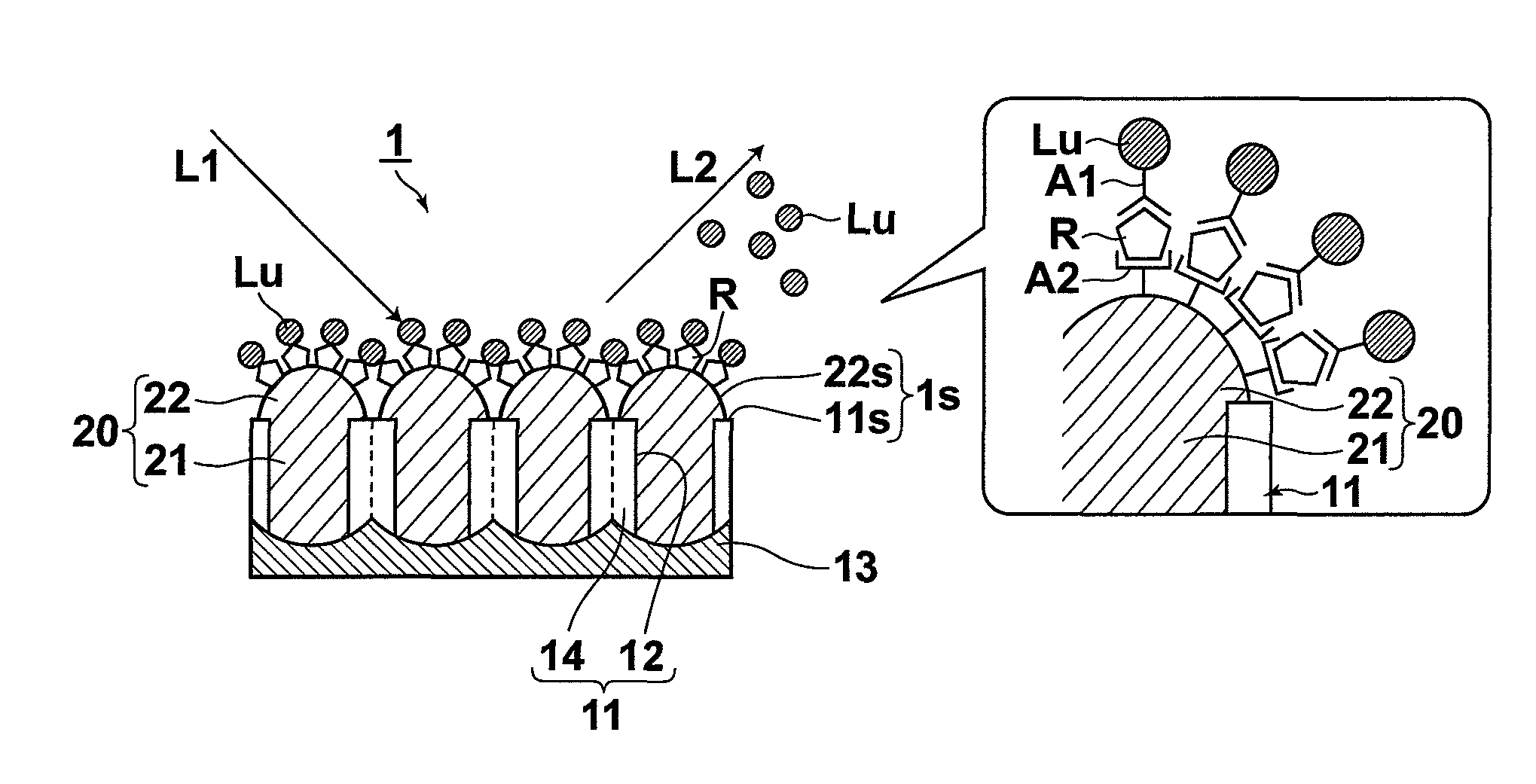
[0036]In the sensor that is structured as described above, when measurement light that has a wavelength that can excite localized plasmons in the metal portion on the sensing surface enters the metal portion, localized plasmons are excited in the metal portion. Therefore, the power of the measurement light is increased in the vicinity of the metal portion by an electric field enhancement effect of the localized plasmons. Hence, it is possible to increase the probability of transition of the fluorescent marker that has bound to the metal portion and to effectively improve the fluorescence efficiency.
[0037]Further, in the sensor of the present invention, one of the two-photon excitation fluorescence and the multi-photon excitation fluorescence of a fluorescent marker is utilized. Therefore, measurement light that has at least twice the wavelength of excitation light for single-photon excitation is used. Hence, it is possible to suppress absorption of the measurement light and emission of fluorescence by a coexisting material and it becomes possible to detect fluorescence at a higher S / N ratio.
[0038]Further, in the sensor of the present invention, it is sufficient if the sensor includes a metal portion, at least a portion of which is exposed at the sensing surface, and in which localized plasmons can be excited. Therefore, the structure of the sensor itself is simple and a complicated optical system is not required in the measurement system. Hence, the structure of the sensing apparatus can be simplified.
[0039]Further, if a transparent insulation layer is formed on the surface of the metal portion, surface modification that selectively binds to a substance to be detected is provided on the surface of the metal portion through the transparent insulation layer. Therefore, direct movement of charges from the fluorescent marker that has bound to the surface modification to the surface of the metal portion is prevented. Hence, there is no risk that fluorescence emitted from the fluorescent marker is weakened by the direct movement of the charges.

Problems solved by technology

Further, some substance may emit unwanted fluorescence.
If such a sensor is used, the prism absorbs excitation light and emits unwanted fluorescence in some cases.
Such absorption of excitation light and emission of fluorescence by coexisting substances or the like, which are not an object of detection, lower the accuracy of detection of fluorescence that should be originally detected.
Therefore, ordinarily, a very expensive pulse laser that has a high peak value is used to obtain sufficient fluorescence.
Further, a complicated optical system is required to emit measurement light and to detect detection light.
Therefore, the sensing apparatus tends to be expensive and complicated.
Further, even if the probability of transition is increased by approximately two digits, when the size of the cross-sectional area of absorption is taken into consideration, it is not recognized that sufficient fluorescence efficiency is obtained.
Therefore, there is still a problem that the fluorescence efficiency has to be improved.

Method used


Image

  • Surface plasmon sensor, sensing apparatus and sensing method
  • Surface plasmon sensor, sensing apparatus and sensing method
  • Surface plasmon sensor, sensing apparatus and sensing method

Examples


Embodiment Construction

Sensor

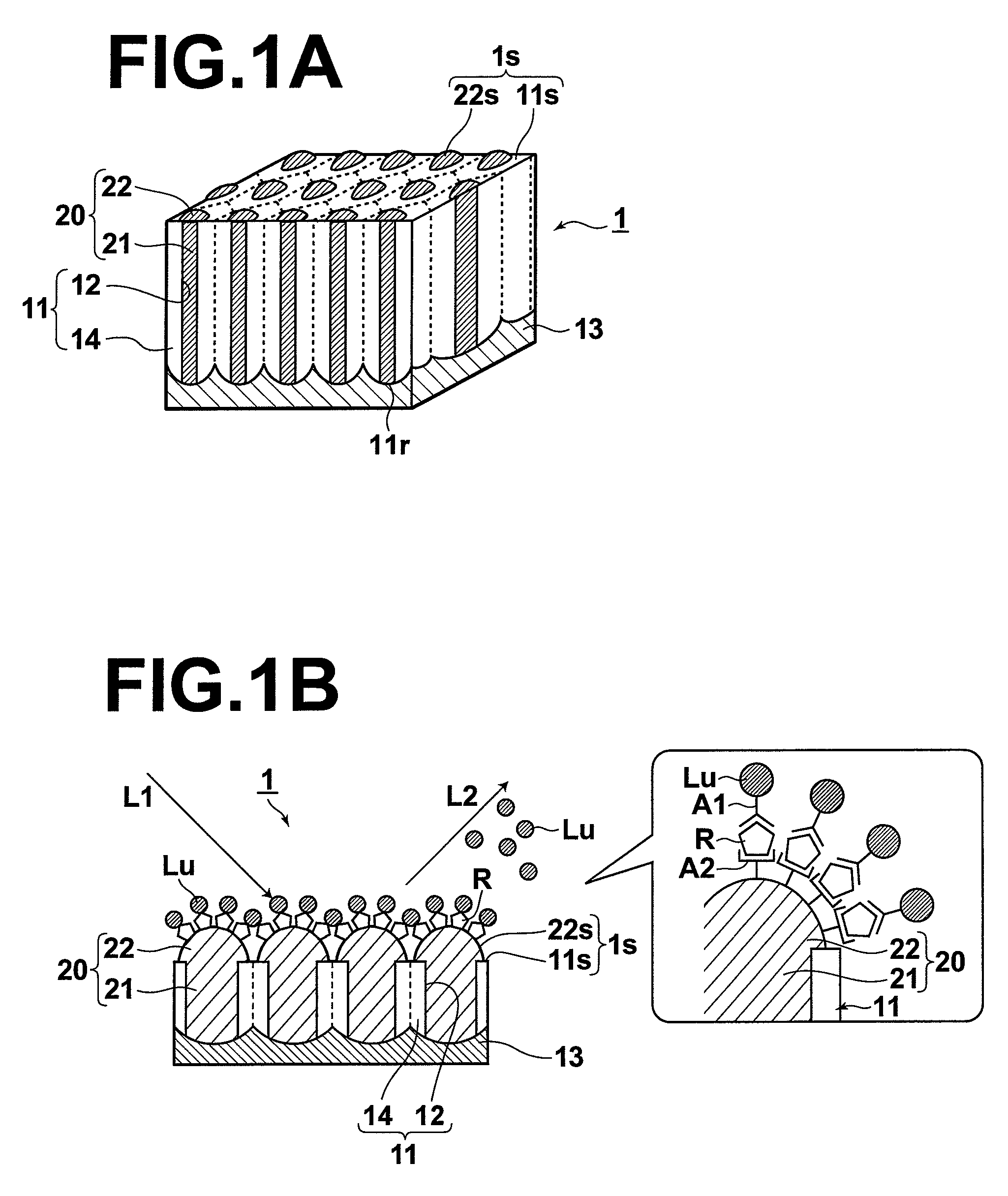
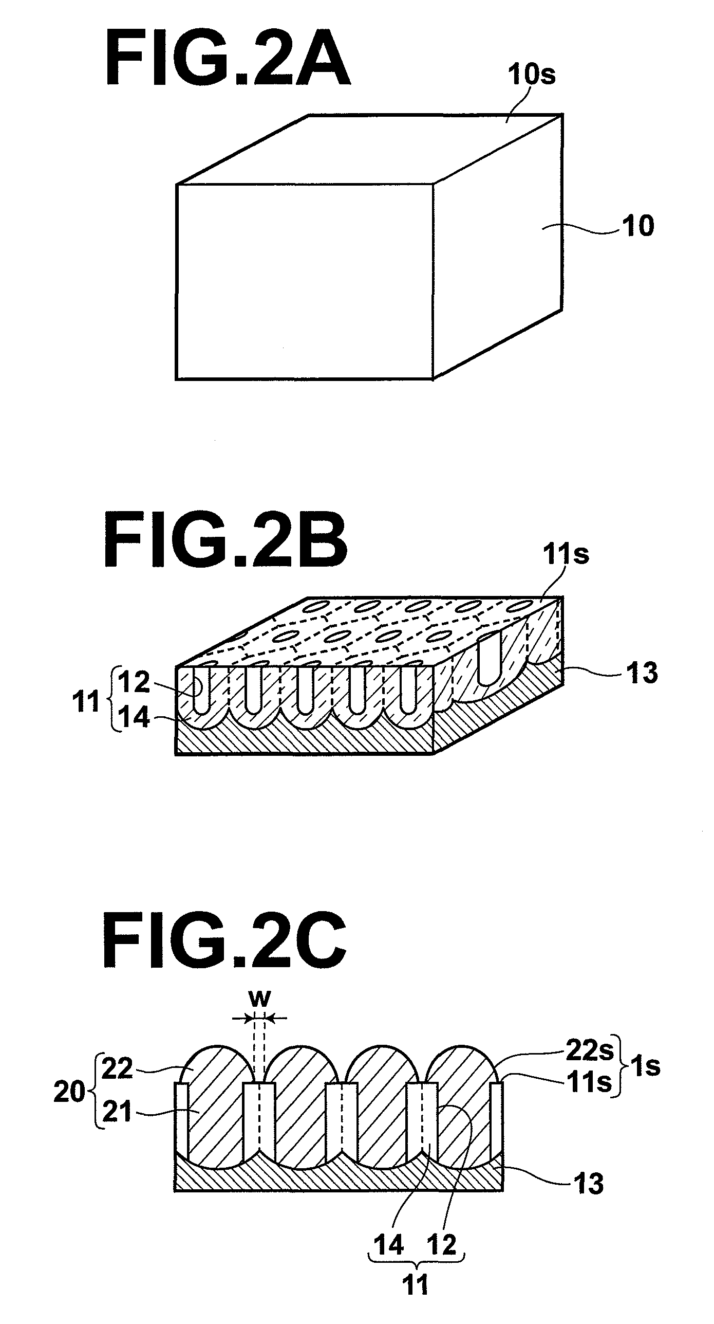
[0053]The structure of a sensor according to an embodiment of the present invention will be described with reference to the attached drawings. FIG. 1A is a perspective view showing the whole structure of the sensor. FIG. 1B is a cross-sectional view of the sensor in the thickness direction of the sensor during sensing. Further, FIG. 1B includes a schematic diagram illustrating a binding state at a sensing surface during sensing. FIGS. 2A through 2C are diagrams illustrating the process of producing the sensor according to the present embodiment.

[0054]A sensor 1 according to the present embodiment is used in sensing, in which a substance R to be detected is marked with a fluorescent marker Lu that selectively binds to the substance R to be detected and one of two-photon excitation fluorescence and multi-photon excitation fluorescence of the fluorescent marker Lu is detected. The sensor 1 includes a sensing surface 1s, to which only the substance R to be detected can bind.

[0055]...


PUM

PropertyMeasurementUnit
diametersaaaaaaaaaa
diameteraaaaaaaaaa
average distanceaaaaaaaaaa

Abstract

A sensor has a sensing surface, to which a specific substance R to be detected can bind. Further, the sensor has a metal portion, at least a portion of which is exposed at the sensing surface, and in which localized plasmons can be excited. The sensor is used in sensing, in which the substance R to be detected is marked with a fluorescent marker Lu that selectively binds to the substance R to be detected and one of two-photon excitation fluorescence and multi-photon excitation fluorescence of the fluorescent marker Lu is detected. Further, the sensing surface is illuminated with measurement light L1 having a wavelength that can excite localized plasmons in the metal portion and that is an absorption wavelength of the fluorescent marker Lu, at which the fluorescent marker Lu emits one of the two-photon excitation fluorescence and the multi-photon excitation fluorescence.

Description

BACKGROUND OF THE INVENTION[0001]1. Field of the Invention[0002]The present invention relates to a sensor that is used in sensing, in which a substance to be detected is marked with a fluorescent marker that selectively binds to the substance to be detected and one of two-photon excitation fluorescence and multi-photon excitation fluorescence of the fluorescent marker is detected. The present invention also relates to a sensing apparatus and a sensing method using the sensor.[0003]2. Description of the Related Art[0004]In recent years, fluorescence measurement methods have been proposed in fluorescent analysis that is performed in immunity measurement and the like in the field of biochemistry. In the fluorescence measurement methods, a sensor having a sensing surface, to which a specific substance to be detected can bind, is used. In the methods, a fluorescent marker that has bound to the substance to be detected is excited by evanescent waves or surface plasmons and the substance t...

Claims


Application Information

Patent Timeline
Patent Type & Authority Patents(United States)
IPC IPC(8): G01N21/64
CPCG01N21/6428G01N21/6452G01N21/648G01N33/54373
Inventor NAYA, MASAYUKI
Owner FUJIFILM CORP
Learn More