Process for multistage residue hydroconversion integrated with straight-run and conversion gasoils hydroconversion steps

a technology of hydroconversion step and hydroconversion gas, which is applied in the direction of hydrocarbon oil cracking, hydrocarbon oil cracking, physical/chemical process catalysts, etc., can solve the problems of increasing the cost of building and operating the overall plant, and affecting the quality of the overall plant. , to achieve the effect of high feedstock throughput ra

Inactive Publication Date: 2011-05-10
INST FR DU PETROLE
View PDF9 Cites 72 Cited by
  • Summary
  • Abstract
  • Description
  • Claims
  • Application Information

AI Technical Summary

Benefits of technology

[0026]It is another object of this invention to provide a method for the processing of individual stage overhead vapors from the residue ebullated-bed hydrocracking reactors in separate distillate ebullated-bed reactors to overcome processing limitations at high feedstock throughput rates for conventional designs.
[0027]It is a further object of the invention to provide a unique integrated design which utilizes distillate ebullated-bed reactors for diesel and vacuum gas oil processing so as to alleviate issues relating to solids and vacuum residue carryover, which would normally be of concern for fixed-bed reactors.

Problems solved by technology

Additionally, some crude oils also have a higher sulfur content, an undesirable characteristic with respect to both processing and product quality.
Generally speaking, the more severe the conditions required to treat a given feedstock (e.g. higher temperature and pressures), the greater the cost to build and operate the overall plant.
However, as the feedstock becomes heavier, has a greater level of impurities, or requires more severe conversion levels, the fixed-bed system becomes less effective and less efficient.
However, this is not thermally efficient since it requires the streams to be depressurized, cooled down and fractionated, resulting in energy loss.
However, even a small amount of entrained vacuum residue and / or fines would render a fixed-bed incapable of processing this feed.
Moreover, if the feedrate is high, and if there are high amounts of external streams also requiring hydroprocessing, a single ebullated-bed reactor may not have sufficient capacity to hydroprocess the streams.

Method used


Image

  • Process for multistage residue hydroconversion integrated with straight-run and conversion gasoils hydroconversion steps
  • Process for multistage residue hydroconversion integrated with straight-run and conversion gasoils hydroconversion steps

Examples


example 1

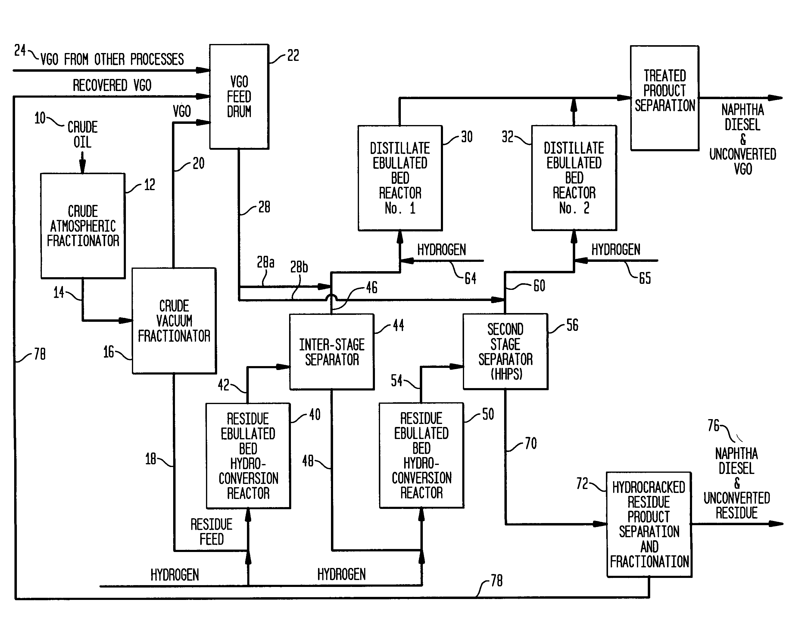
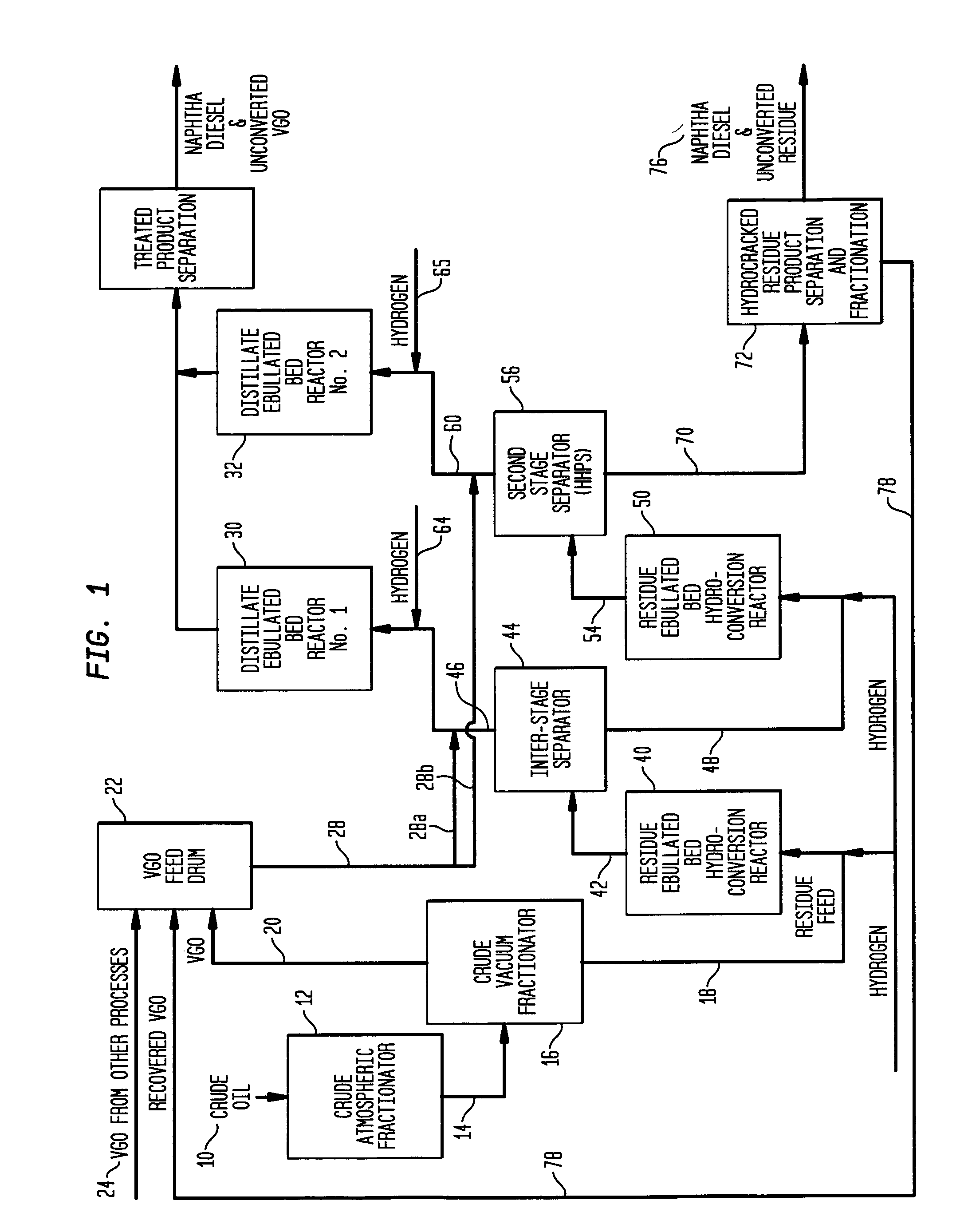
[0057]Vacuum residue feedstock is processed in a two-stage in series residue ebullated-bed unit. The feedrate to the plant is relatively high (>50,000 BPSD) and near the limit for a single train plant. The vacuum residue conversion system utilized in the example are residue ebullated-bed reactors. In addition to the vacuum residue feed to the residue ebullated-bed reactors, there are other VGO boiling range feedstocks (straight run, coker VGO and FCC cycle oils), which also require hydrotreatment and it is desirable to coprocess these streams in separate distillate ebullated-bed reactors along with the residue ebullated-bed overhead material which contains product diesel and vacuum gas oils. A summary of the feedstocks for this example is shown in Table 1.

[0058]This high feedrate and the need to minimize initial investment necessitated the use of interstage separation where a separation vessel between the residue ebullated-bed reactors is used to remove the gas and unreacted hydroge...


PUM

PropertyMeasurementUnit
boiling pointaaaaaaaaaa

Abstract

This invention relates to a novel integrated hydroconversion process for converting heavy atmospheric or vacuum residue feeds and also converting and reducing impurities in the vacuum gas oil liquid product. This is accomplished by utilizing two residue hydroconversion reaction stages, two vapor-liquid separators, and at least two additional distillate ebullated-bed hydrocracking / hydrotreating reaction stages to provide a high conversion rate of the residue feedstocks.

Description

FIELD OF THE INVENTION[0001]This invention relates to a novel integrated hydroconversion process for converting heavy hydrocarbon feeds containing vacuum residue and converting and reducing impurities in the straight run and conversion product vacuum gas oil liquids. This is accomplished by utilizing two residue ebullated-bed hydroconversion reaction stages, two vapor-liquid separators, and at least two additional distillate ebullated-bed hydrocracking / hydrotreating reaction stages.[0002]In a two-stage residue hydroconversion reactor system, the atmospheric or vacuum residue feed and hydrogen react with a catalyst in the first residue hydroconversion stage to produce lighter hydrocarbons. The stage one effluent is thereafter separated in an interstage separator which separates the effluent into a liquid phase and a vapor phase.[0003]The liquid phase from this interstage separator is then fed to the second residue hydroconversion reaction stage for additional conversion and impurity ...

Claims


Application Information

Patent Timeline
Patent Type & Authority Patents(United States)
IPC IPC(8): C10G65/02
CPCC10G7/06C10G45/16C10G65/12C10G65/02C10G65/10C10G47/26
Inventor COLYAR, JAMES J.DUDDY, JOHN
Owner INST FR DU PETROLE
Why Eureka
Try Eureka