
System and method for generation of high pressure air in an integrated gasification combined cycle system

a gasification combined cycle and high-pressure air technology, applied in steam engine plants, machines/engines, combustible gas production, etc., can solve the problems of significant power consumption in the compression stage, significant equipment installation and operational cost for the deployment of itm technology in the igcc system, and reduce the output and net efficiency of the plan

Inactive Publication Date: 2011-05-24
SIEMENS ENERGY INC
View PDF11 Cites 3 Cited by
  • Summary
  • Abstract
  • Description
  • Claims
  • Application Information

AI Technical Summary

Benefits of technology

"The present invention relates to integrated gasification combined cycle (IGCC) power plants. The invention provides a more efficient and cost-effective way to generate power from coal or biomass. The invention uses a single compressor to generate two compressed air streams, one for the gasification system and one for the gas turbine system. This eliminates the need for throttling of the gas turbine compressor outlet stream, which results in a loss of efficiency. The invention also integrates the ITM air separation technology with the gasification system, reducing the need for high-pressure oxygen. The technical effects of the invention include improved efficiency, reduced emissions, and reduced capital and operational costs."

Problems solved by technology

One disadvantage of using cryogenic systems for oxygen separation is that the compression stage requires significant power consumption.
This reduces the plant output and net efficiency.
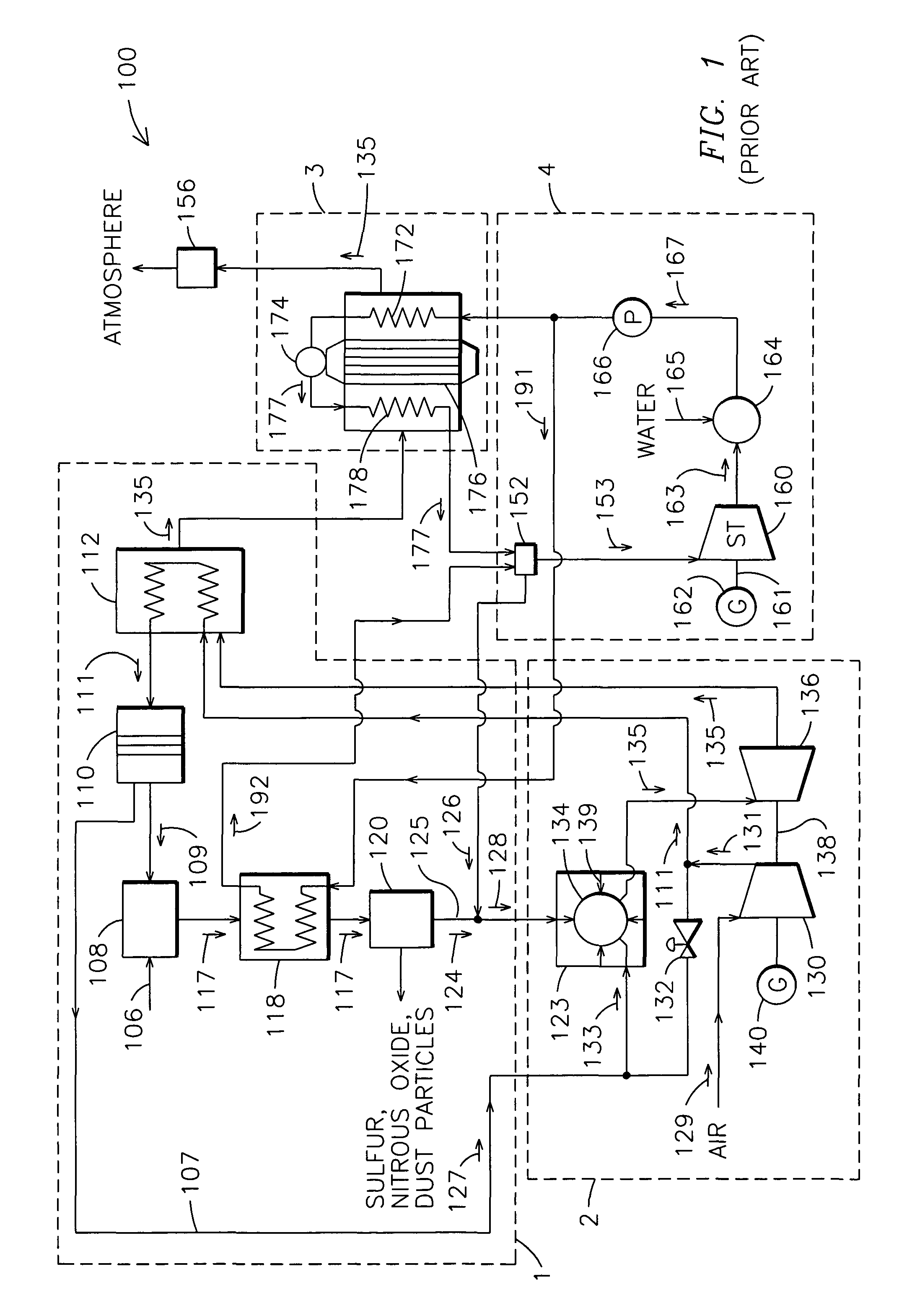
A compressor and an air pre-heater are generally employed to provide the high temperature, high pressure air stream, adding significant equipment installation and operational cost for deployment of the ITM technology in IGCC systems.

Method used


Image

  • System and method for generation of high pressure air in an integrated gasification combined cycle system
  • System and method for generation of high pressure air in an integrated gasification combined cycle system
  • System and method for generation of high pressure air in an integrated gasification combined cycle system

Examples


Embodiment Construction

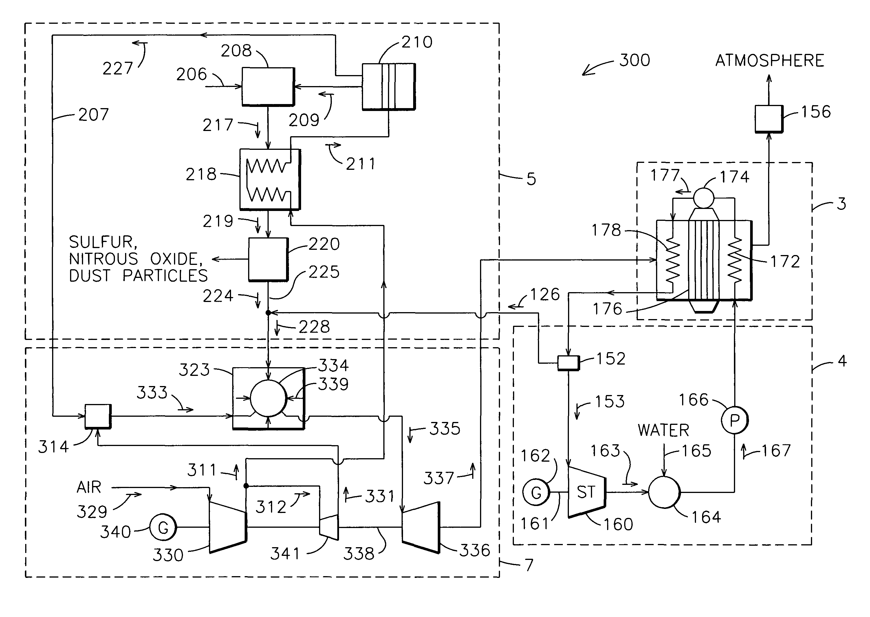
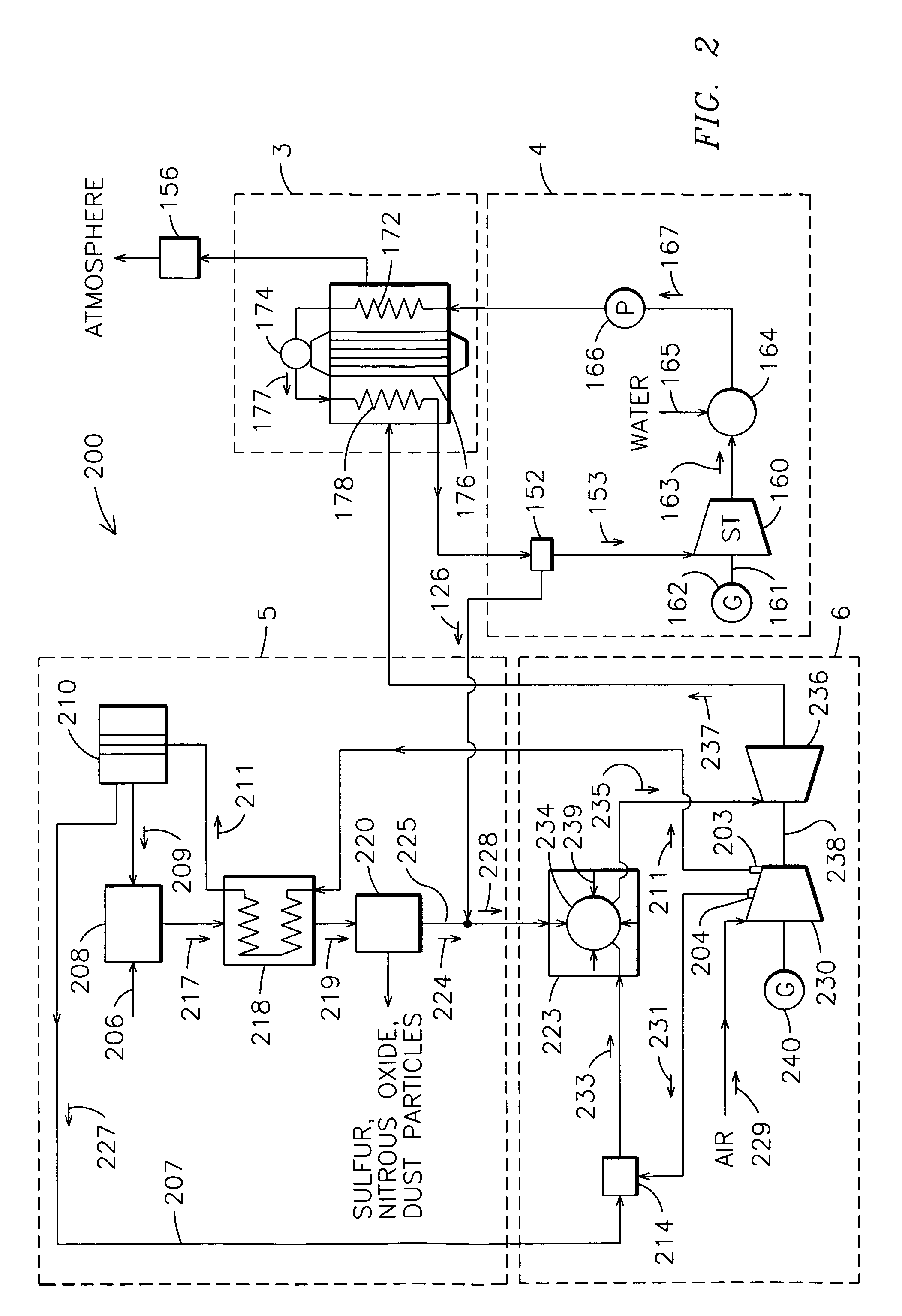
IGCC systems employing the ITM air separation technology require two compressed air streams, one for the ITM air separation process and one for combustion of the fuel mixture in a gas combustor. The ITM process requires compressed air, generally in the range of 150-500 psia. The gas combustor of the IGCC gas turbine system requires compressed air, generally in the range of 120 psia-475 psia. It is now recognized as advantageous to generate two compressed air streams from a single compressor. This approach, using, for example, a compressor having multipressure outlets, reduces capital equipment costs as well as the operational costs of IGCC systems.

In the past, high pressure oxygen-depleted air produced by the ITM has been injected into the fuel mixture entering the combustor of the IGCC gas turbine system. This facilitates temperature control and NOx emission reduction. The pressure of the oxygen-depleted air relative to the compressed air supplied to the ITM ASU is reduced, due to ...


PUM


Abstract

An integrated gasification combined cycle system. In one embodiment (FIG. 2) a system (200) includes an ion transport membrane air separation unit (210) for producing oxygen-enriched gas (209) and oxygen-depleted air (227), a gasification system (5) for generating syngas with the oxygen-enriched gas (209), a gas combustor (234) for reacting the syngas (224), and a subsystem configured to provide a first stream of air to the combustor (234) at a first pressure and to provide a second stream of air to the air separation unit (210) at a second pressure greater than the first pressure. The subsystem includes a compressor (230) having multi-pressure outlets (203, 204).

Description

FIELD OF THE INVENTIONThe present invention relates generally to power generation systems, and more particularly, to integrated gasification combined cycle systems.BACKGROUND OF THE INVENTIONIntegrated Gasification Combined Cycle (IGCC) systems are an economically attractive alternative to Natural Gas Combined Cycle systems (NGCC), as the systems can use more abundant fuel sources such as coal or biomass. IGCC systems gasify the low heating value fuel and produce a mixture comprising hydrogen and carbon monoxide. IGCC systems also have greater potential for efficiency improvement and a decrease in undesirable emissions compared to conventional coal-fired steam power plants.IGCC power plants having oxygen-blown gasifiers to generate syngas require a relatively pure stream of oxygen gas. Production of this oxygen supply can be achieved by various means. A well-known technique is the cryogenic air separation method, in which the partial pressure differences between oxygen and other air...

Claims


Application Information

Patent Timeline
Patent Type & Authority Patents(United States)
IPC IPC(8): B01D59/12F02C3/26
CPCB01D53/229C01B3/32C01B13/0251C10J3/00F01K23/068F02C3/28Y02E20/16B01D2257/102C01B2203/025C01B2203/04C01B2203/06C01B2203/08C01B2203/0894C01B2203/84C01B2210/0046C10J2300/0916C10J2300/093C10J2300/0959C10J2300/165C10J2300/1671C10J2300/1675C10J2300/1861C10J2300/1869C10J2300/1876C10J2300/1884C10J2300/1892Y02E20/18B01D2256/12Y02P20/145
Inventor SULLIVAN, TERRENCE B.
Owner SIEMENS ENERGY INC
Learn More