
Circuit board structure and fabrication method thereof

a technology of circuit board and dielectric layer, which is applied in the direction of transportation and packaging, chemical apparatus and processes, and applications of non-metallic protective coatings. it can solve the problems of difficult control of the roughening process, the circuit layer can easily detach from the dielectric layer, and the roughening process becomes much more difficult. , to achieve the effect of preventing the formation of excessive roughness, reducing the formation of rough surfaces, and increasing the bonding force of the dielectric layer

Active Publication Date: 2011-06-21
UNIMICRON TECH CORP
View PDF4 Cites 7 Cited by
  • Summary
  • Abstract
  • Description
  • Claims
  • Application Information

AI Technical Summary

Benefits of technology

[0009]According to the above drawbacks, an objective of the present invention is to provide a circuit board structure and a fabrication method thereof so as to strengthen the bonding force between the dielectric layer and the circuit layer of the circuit board.
[0010]Another objective of the present invention is to provide a circuit board structure and a fabrication method thereof so as to maintain satisfactory electrical performance of the circuit board, thereby ensuring the quality and reliability of the circuit board.
[0011]A further objective of the present invention is to provide a circuit board structure and a fabrication method thereof whereby a fine circuit can be formed on the circuit board so as to meet the demand for high-density layouts.
[0012]In order to attain the above and other objectives, the present invention provides a circuit board structure which comprises: a circuit board with a circuit layer thereon; a reactant formed on the surface of the circuit layer, wherein the reactant is an organic metallic polymer having a polymer end and a metal ion end; and a dielectric layer formed on the reactant and the circuit board so as to form a metallic bond between the metal ion end and the circuit layer and form a chemical bond between the polymer end and the dielectric layer, thereby strengthening the bonding force between the dielectric layer and the circuit board.
[0015]The present invention further provides a fabrication method of a circuit board structure, comprising: providing a circuit board with a circuit layer thereon; forming a reactant on the surface of the circuit layer, wherein the reactant is an organic metallic polymer having a polymer end and a metal ion end; and forming a dielectric layer on the reactant and the circuit board such that a metallic bond can be formed between the metal ion end and the circuit layer and a chemical bond can be formed between the polymer end and the dielectric layer, thereby strengthening the bonding force between the dielectric layer and the circuit board.
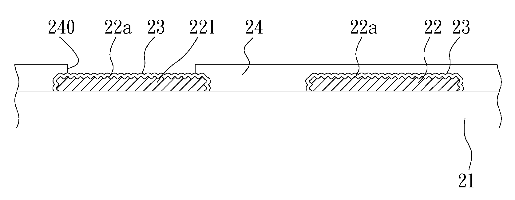
[0019]Therefore, the present invention comprises forming a reactant on the surface of a circuit layer, or performing micro-etch pretreatment on the circuit layer beforehand so as to form a micro-rough surface on the circuit layer and then forming a reactant on the surface of the circuit layer, wherein the reactant is made of an organic metallic polymer having a polymer end and a metal ion end. The polymer end is bonded to the surface of the circuit board through a chemical bond so as to increase the bonding force of the dielectric layer on the circuit layer. The polymer end and the dielectric layer have similar properties and are bonded together through adsorption between molecules, the metal ion end and the circuit layer have similar properties and are bonded together through a metallic bond. Thus, the bonding force between the circuit layer and the dielectric layer is strengthened through the reactant. Further, the present invention prevents formation of excessively roughened surfaces and therefore prevents undercutting. The desirable shape of the circuit remains intact in the present invention, and thus satisfactory electrical performance of the circuit board is maintained, thereby ensuring the quality and reliability of the circuit board. Furthermore, the present invention is applicable to a fine circuit process. Thus, the present invention overcomes the drawbacks of a conventional etching process.

Problems solved by technology

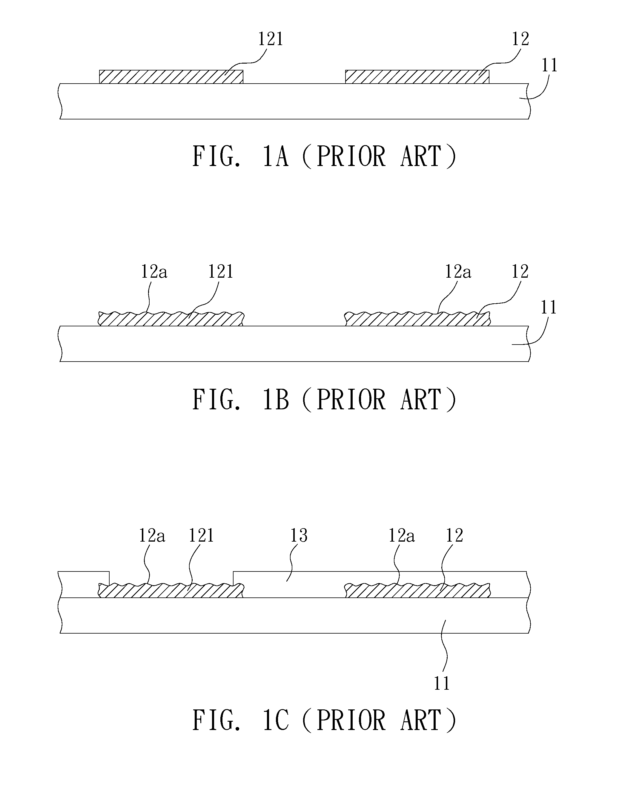
However, the roughening process is difficult to control.
If the surface of the dielectric layer is not efficiently roughened, the circuit layer can easily detach from the dielectric layer.
As for circuit boards having fine circuit, the roughening process becomes much more difficult as an efficient bonding area between the fine circuit and the dielectric layer is reduced.
However, it is difficult to achieve a uniformly etched surface, and any slight change of shape or dimensions of the circuit layer can affect the electrical quality.
The conventional roughening process often ends up with uneven thickness and uncontrollable line width of a circuit layer, especially the circuit layer of high-density circuit boards, which affects the electrical quality of the circuit boards and makes it difficult to be applied in circuit boards having a fine circuit.
For circuit boards with a high-density layout and a small line width, a badly timed etching process is likely to sever a circuit and result in an open circuit, or tends to undercut the circuit layer and therefore taper the cross-section of the circuit layer downward and reduce the cross-sectional area of the circuit layer, and in consequence the signal transmission quality and electrical performance of the circuit board are adversely affected.
On the other hand, an etching process may be too short to roughen the surface of the circuit layer sufficiently, such that the dielectric layer formed on the circuit layer readily detaches from the circuit layer, thereby resulting in poor bonding between the circuit layer and the dielectric layer and adversely affecting the quality of products.

Method used


Image

  • Circuit board structure and fabrication method thereof
  • Circuit board structure and fabrication method thereof
  • Circuit board structure and fabrication method thereof

Examples


first embodiment

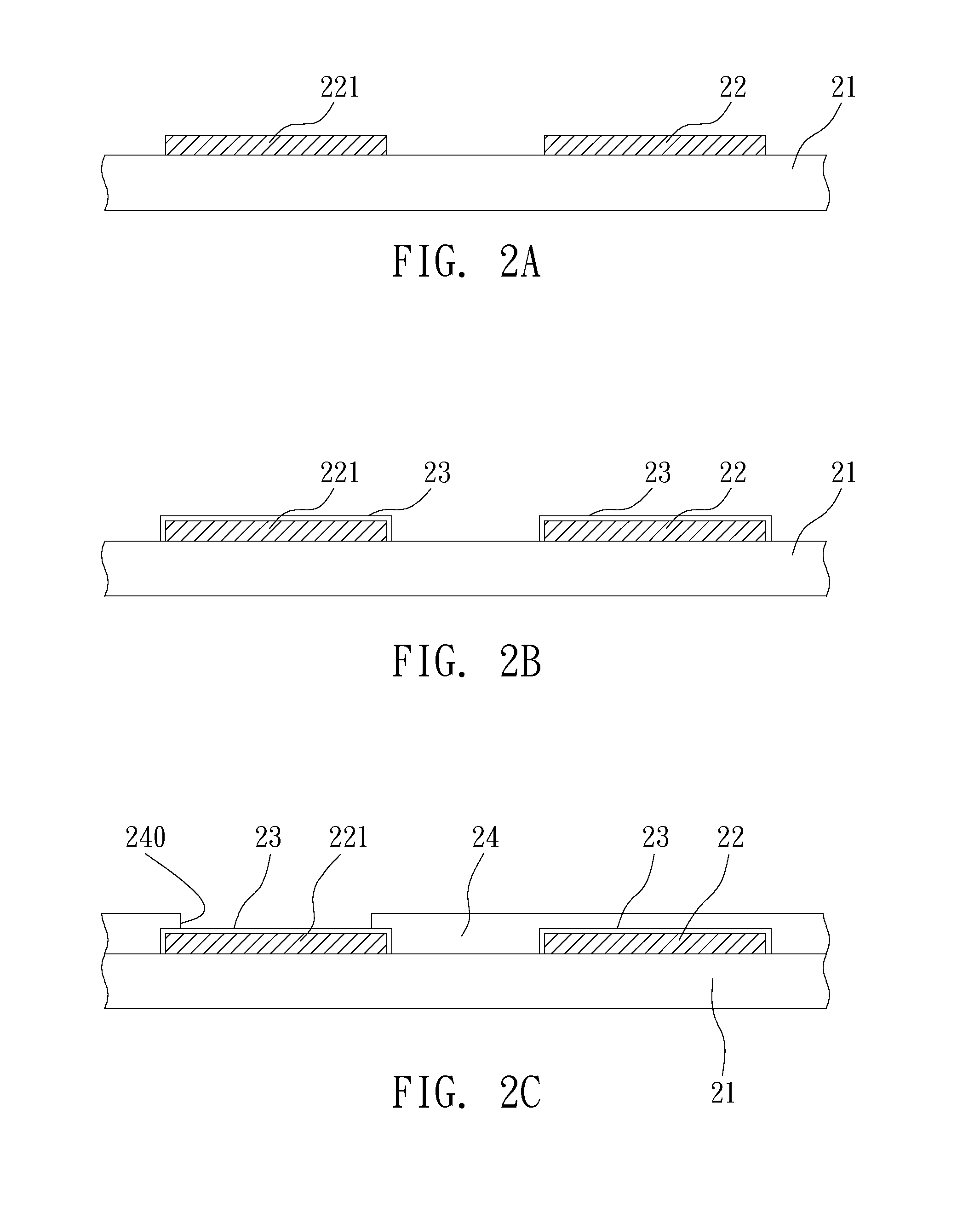
[0024]FIGS. 2A to 2C are cross-sectional views showing a fabrication method of a circuit board structure according to the first embodiment of the present invention.

[0025]Referring to FIG. 2A, a circuit board 21 is provided. The circuit board 21 is a single-layer or multi-layer circuit board required for a front-end circuit process. The circuit board 21 has a circuit layer 22 thereon. The circuit layer 22 comprises a plurality of electrically connecting pads 221 (or known as electrically connecting lands 221). The circuit layer 22 is made of Au, Ag, Cu, Fe, Pd, Pb, Sn, Bi, Sb, Zn, Ni, Zr, Mg, In, Te, or Ga.

[0026]Referring to FIG. 2B, a reactant 23 is formed on the circuit board 21, the reactant 23 formed being limited to the surface of a circuit layer 22, wherein the reactant 23 is an organic metallic polymer with a polymer end and a metal ion end. The polymer end is bonded to the surface of the circuit board 21 by a chemical bond. The metal ion end of the reactant 23 can be bonded t...

second embodiment

[0031]FIGS. 3A to 3D are cross-sectional views showing a fabrication method of a circuit board structure according to the second embodiment. The second embodiment differs from the first embodiment in that the second embodiment further discloses performing micro-etch pretreatment on the circuit layer.

[0032]Referring to FIG. 3A, a circuit board 21 with a circuit layer 22 thereon is provided. The circuit layer 22 has a plurality of electrically connecting pads 221 (or known as electrically connecting lands 221).

[0033]As shown in FIG. 3B, micro-etch pretreatment is performed on the surface of the circuit layer 22 so as to form a micro-rough surface 22a on the circuit layer 22. The micro-rough surface 22a is a fine, rough surface.

[0034]As shown in FIG. 3C, a reactant 23 is formed on the circuit layer 22, the reactant 23 formed being limited to the surface of a circuit layer 22, wherein the reactant 23 has a polymer end and a metal ion end. The polymer end can be bonded to the surface of ...


PUM

PropertyMeasurementUnit
bonding forceaaaaaaaaaa
dielectricaaaaaaaaaa
densityaaaaaaaaaa

Abstract

A circuit board structure and fabrication method thereof are disclosed, including: a circuit board with a circuit layer thereon; a reactant formed on the surface of the circuit layer, wherein the reactant is an organic metallic polymer having a polymer end and a metal ion end; and a dielectric layer formed above the reactant and the circuit board, thus forming a metallic bond between the metal ion end of the reactant and the circuit layer and forming a chemical bond between the polymer end of the reactant and the dielectric layer. Owing to enhanced bonding between the dielectric layer and the circuit board, electrical performance of the circuit board structure is improved, and the demand for fine circuits is met.

Description

BACKGROUND OF THE INVENTION[0001]1. Field of the Invention[0002]The present invention relates generally to circuit board structures and fabrication methods thereof, and more particularly, to a circuit board structure and fabrication method thereof capable of improving the bonding between the dielectric layer and the circuit layer of the circuit board structure.[0003]2. Description of Related Art[0004]High-density multi-layer circuit boards with fine circuit have become a main trend of future development, wherein the quality of circuit layers of the circuit boards for signal transmission is an important factor in electrical performance of the circuit boards.[0005]With the line-to-space ratio (L / S) decreasing, circuit boards nowadays are subject to a slight change of shape or dimensions as far as electrical quality is concerned, especially when circuit boards operate at a high-frequency state.[0006]In addition, in a conventional circuit build-up process, the surface of a dielectric la...

Claims


Application Information

Patent Timeline
Patent Type & Authority Patents(United States)
IPC IPC(8): H05K1/02
CPCH05K3/389H05K3/28H05K3/4644Y10T428/24917Y10T29/49128Y10T29/49124H05K2203/121
Inventor SHIH, CHAO-WEN
Owner UNIMICRON TECH CORP
Learn More