System and method for imposing thermal gradients on thin walled test objects and components

a thin walled test object and thermal gradient technology, applied in the direction of gas turbine engine testing, machines/engines, instruments, etc., can solve the problems of increasing the cost of engine programs, increasing the number of engine programs, and not having a cost-effective way to conduct representative tmf testing. , to achieve the effect of enhancing the effectiveness of high-mass flow fluid, thin walls, and large thermal and/or pressure gradients

Active Publication Date: 2011-06-28
SCHENCK USA CORP
View PDF10 Cites 46 Cited by
  • Summary
  • Abstract
  • Description
  • Claims
  • Application Information

AI Technical Summary

Benefits of technology

[0018]The disclosed system and method employs combustor technology with a turbocharger to create a test facility that emulates engine conditions without excessive energy consumption and high cost. The combustor technology and turbocharger are configured to achieve rapid representative thermal excursions within the test component to attain adequate heat flux to model conditions in a gas turbine engine. A compressed air source may also be used in combination with the turbocharger or combustor technology.
[0019]Energy consumption and costs are reduced by reusing and recapturing energy in the high mass flow, high temperature fluid output from the test chamber. The recaptured output can be used to drive other system components. Impingement cooling air, which may be non-uniform or focused within the test component, may also be used. The heating and cooling aspects of the system can be separately controlled and cycled on an independent basis to achieve specific testing profiles. The test component can be readily instrumented or be exposed for measurement with greater ease, reduced complexity and reduced cost than is typically possible in a corresponding full gas turbine engine test. The configuration of the test chamber can be specific to the test component to contribute to duplicating relative parameters, especially in a boundary layer area of the test component. The test chamber can also be configured to limit fluid mass flow to reduce thermal energy input specifications and increase efficiency.

Problems solved by technology

Given the extensive testing used to generate durability and life prediction models, and the cost of full-up engine tests ($6M+ each), no cost-effective way to conduct representative TMF testing is presently available.
Current blade / vane design methods are also very costly, often requiring several iterations to achieve a “best effort” solution, resulting in increases of many millions of dollars and months of schedule to an engine program.
Additionally, TMF related failures in engine hot sections are a critical factor driving class A mishaps, and low total accumulated cycles (TAC) useful life, Mean Time Between Failure (MTBF), and Mean Time Between Maintenance (MTBM).
Current finite element analysis (FEA) software can approximate the stresses (mechanical and thermal) on blades and vanes, but without correlation of boundary conditions to empirical testing, it is difficult to know how accurate the model is and what risk the deviation from the conservative approach represents.
However, these specimens are typically constructed for thermal material tests, and often have a geometry that is not necessarily representative of practical blade and vane geometry.
Such tests do not wholly represent engine operating conditions and the resulting data is subject to very conservative interpretation.
A major limiting factor to achieving rapid representative thermal excursions within an appropriately representative test component is the inability to attain adequate heat flux under representative conditions.
Components in the flow path withstand an extremely hostile environment.
Attempting to control and phase thermal gradients on gas turbine engine components has so far proven highly impractical with existing methods.
As a result, analytically based life prediction models have fallen well short of accurately predicting component life with the result of imposing serious financial burdens on operators.
A major limiting factor to achieving rapid representative thermal excursions within the test component is the inability to attain adequate heat flux under representative conditions.
The test component can have relatively thin walls and may be provided with internal impingement cooling, which may be non-uniform.

Method used


Image

  • System and method for imposing thermal gradients on thin walled test objects and components
  • System and method for imposing thermal gradients on thin walled test objects and components
  • System and method for imposing thermal gradients on thin walled test objects and components

Examples


Embodiment Construction

[0033]This application claims the benefit of U.S. Provisional Application No. 61 / 065,757, filed Feb. 14, 2008, the entire disclosure of which is hereby incorporated herein by reference.

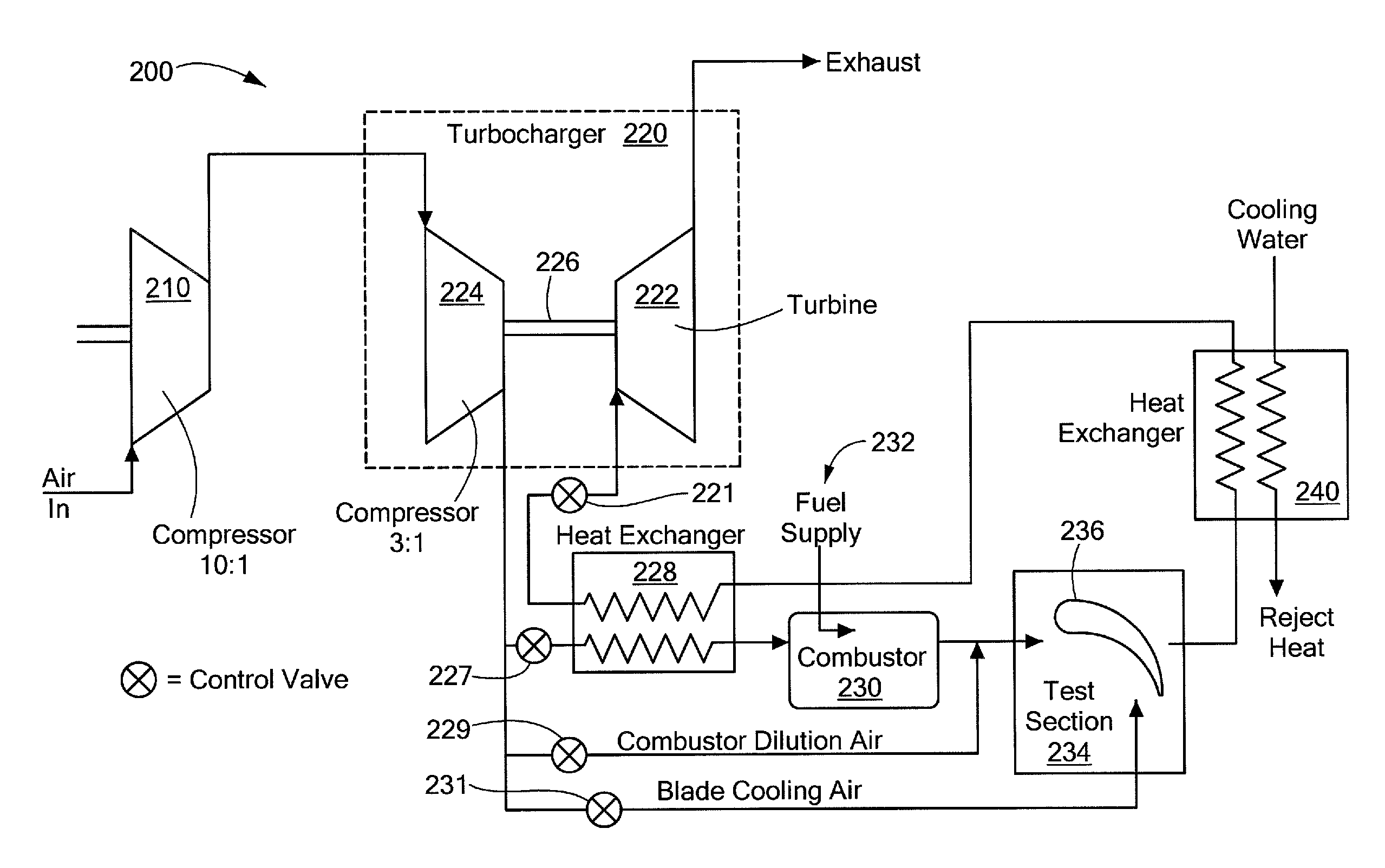
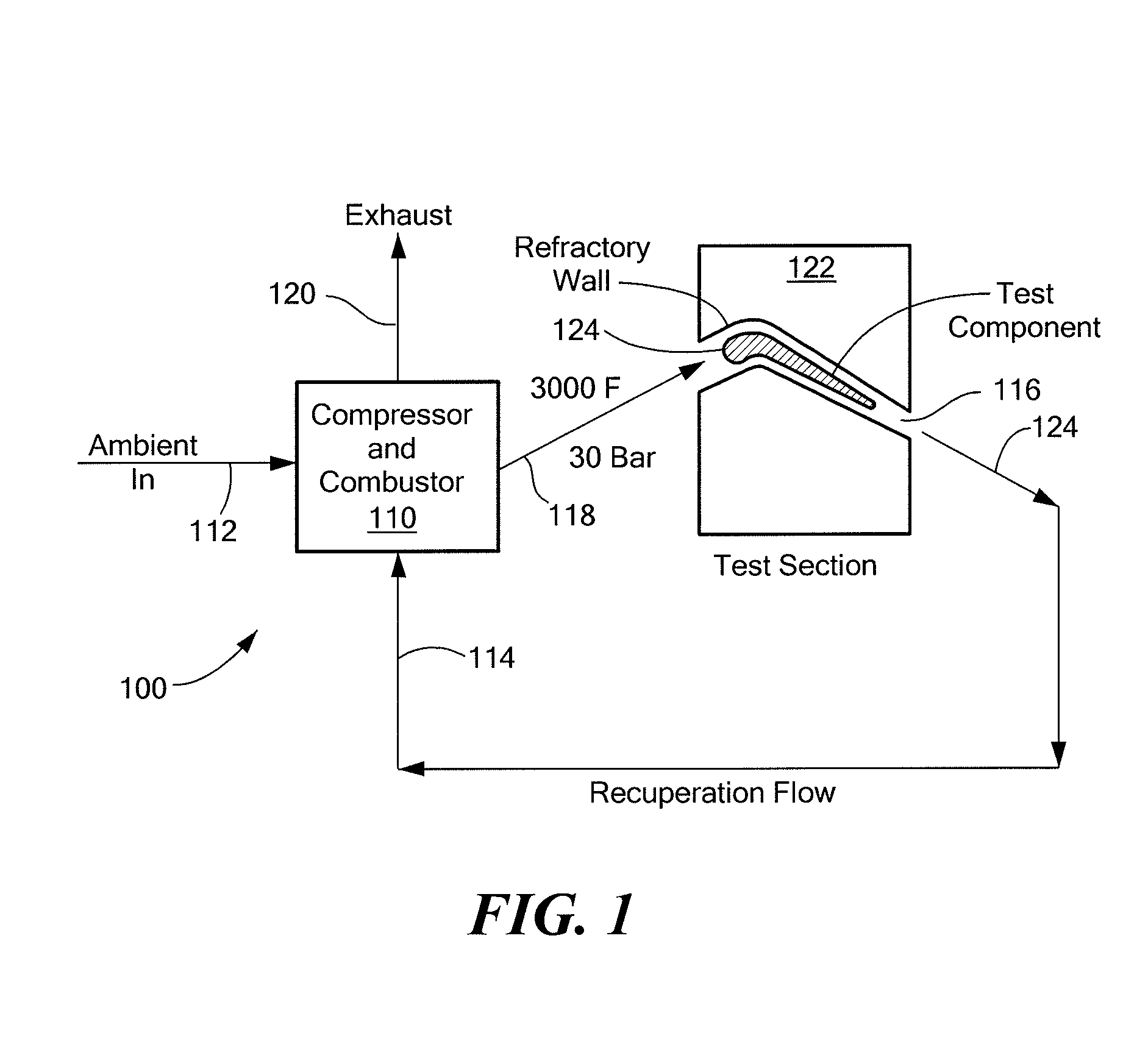
[0034]In accordance with the disclosed system and method, there is provided a test facility that has a test chamber for housing a test component upon which is imposed a relatively large (steep) through-wall temperature gradient, such as, for example, 400° F. The test component may also be subjected to axial load and to internal impingement cooling that may be uniform, non-uniform or focused to a target location on the test component. The test facility provides an emulation of operational thermal and mechanical fatigue loads (TMF) in a gas turbine engine. The test facility can be used to contribute to producing enhanced service life predictions, as well as improved designs for gas turbine engine components.

[0035]In a gas turbine engine, parameter variation may realistically be carried out over a very n...


PUM


Abstract

A test facility provides high temperature, high pressure and high mass flow fluid to a test object to form a relatively large thermal gradient on the object. Energy in the fluid is recuperated to drive system components, such as a heat exchanger and a turbocharger compressor. A test chamber housing the test object can be arranged to conform to a contour of the test object. A control system permits independent variation of pressure, temperature, cooling fluid and fluid velocity, as well as mechanical loading on the test object. Noncontact, optical inspection measurement techniques can be employed to measure test chamber and / or test object parameters. The test object can be configured to direct cooling airflow to permit various temperature or pressure gradients to be implemented. The test facility is relatively inexpensive to operate and provides a significant cost advantage over testing conducted in a full gas turbine engine.

Description

CROSS REFERENCE TO RELATED APPLICATIONS[0001]This application claims the benefit of U.S. Provisional Application No. 61 / 065,757, filed Feb. 14, 2008, the entire disclosure of which is hereby incorporated herein by reference.STATEMENT REGARDING FEDERALLY SPONSORED RESEARCH OR DEVELOPMENT[0002]This invention was made with government support under contract No. FA8650-08-M-2830 awarded by the United States Air Force. The government has certain rights in the invention.BACKGROUND OF THE INVENTION[0003]1. Field of the Invention[0004]The disclosed system and method relate generally to generating a relatively large, or steep, thermal gradient on a test object, and relates more particularly to a test facility for generating a steep thermal gradient across a thin wall of a test object or actual component, particularly gas turbine engine components.[0005]2. Description of Related Art[0006]Current thermal and mechanical fatigue load (TMF) test methods do not include steep temperature gradients a...

Claims


Application Information

Patent Timeline
Patent Type & Authority Patents(United States)
IPC IPC(8): G01M15/14
CPCF01D25/285G01M99/002F05D2260/80Y02T50/67Y02T50/60
Inventor SONNICHSEN, H. ERICMURNER, ROBERT L.WOLF, THOMAS L.
Owner SCHENCK USA CORP
Why Eureka
Try Eureka