Electro-optic apparatus and electronic equipment

a technology of electro-optic equipment and electronic equipment, applied in the direction of static indicating devices, instruments, printed circuit non-printed electric components association, etc., can solve the problems of reducing the performance of electro-optic panels, power consumption increases, and the probability of thermal runaway or thermal rupture is reduced, and the effect of efficient radiation

Active Publication Date: 2011-06-28
SEIKO EPSON CORP
View PDF30 Cites 11 Cited by
  • Summary
  • Abstract
  • Description
  • Claims
  • Application Information

AI Technical Summary

Benefits of technology

[0007]An advantage of some aspects of the invention is that there is provided an electro-optic apparatus which is able to radiate heat generated by an integrated circuit chip efficiently and an electro-optic apparatus mounting case and electronic equipment.

Problems solved by technology

Accordingly, the electro-optic panel is likely to rise in temperature, which lowers a performance of the electro-optic panel.
However, in the integrated circuit chip described above, power consumption increases in association with improvement of the throughput, and calorific power due to this operation increases.
Therefore, there arises a technological problem such that the electro-optic apparatus is likely to be subjected to thermal runaway or thermal rupture due to the heat generated by the integrated circuit chip.
In contrast, according to the technology described in JP-A-2003-15104 and JP-A-2002-366046, there is a technological problem such that it is not suitable at least for heat radiation of the integrated circuit chip.
According to the study of the inventors of this application, the drive circuit included in the integrated circuit unit is generally becoming complicated and developed by a demand of high definition of display images.
Therefore, cooling of the integrated circuit unit is insufficient with a natural convection of air or a forced convection by a fan, and it is turned out that the electro-optic apparatus is likely subjected to thermal runaway or thermal rupture due to the heat generated by the integrated circuit unit.

Method used


Image

  • Electro-optic apparatus and electronic equipment
  • Electro-optic apparatus and electronic equipment
  • Electro-optic apparatus and electronic equipment

Examples


first embodiment

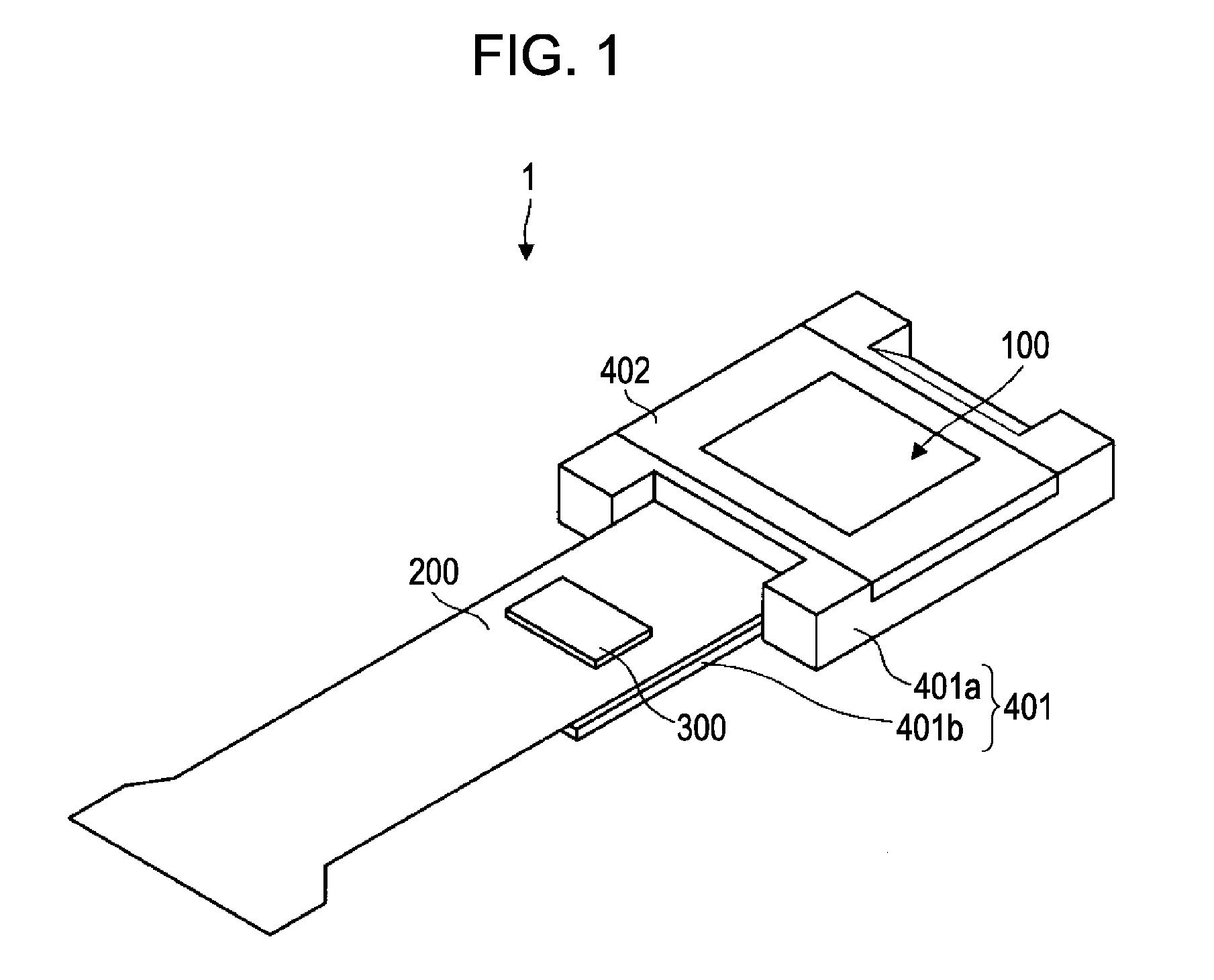
[0056]Referring now to FIG. 1 to FIG. 6, a first embodiment of the electro-optic apparatus in the invention will be described. The scales of the respective layers and members are different from the actual scale throughout the drawings in order to make these layers and members recognizable in the drawings.

[0057]First of all, referring now to the drawings, a general configuration of a liquid crystal device in the first embodiment will be described. FIG. 1 is a perspective view of the liquid crystal device according to the first embodiment.

[0058]In FIG. 1, a liquid crystal device 1 includes a liquid crystal panel 100, a wiring board 200 including a plurality of signal lines electrically connected to the liquid crystal panel 100, and a drive IC chip 300 provided on the wiring board 200 and electrically connected to at least part of the plurality of signal lines, and including at least part of a drive circuit for driving the liquid crystal panel 100. The drive IC chip 300 includes, for e...

first modification

[0079]Referring now to FIG. 7 and FIG. 8, a first modification of the electro-optic apparatus according to the first embodiment will be described. FIG. 7 is a plan view of a liquid crystal device according to the first modification when viewed from the side of the opposed substrate, which is similar to FIG. 4, and FIG. 8 is a cross-sectional view taken along the line VIII-VIII in FIG. 7.

[0080]As shown in FIG. 7 and FIG. 8, a radiation fin 421 is arranged on the heat radiating portion 401b. Typically, the radiation fin 421 and the heat radiating portion 401b are bonded to each other by the mold agent or the like. The radiation fin 421 is formed of metal having high coefficient of heat conductivity such as aluminum, for example. The material to form the radiation fin 421 and the material to from the frame 401 may either be different or the same.

[0081]With the provision of the radiation fin 421, the surface area which contributes to the radiation is increased, and the good airflow is a...

second modification

[0083]Referring now to FIG. 9 and FIG. 10, a second modification of the electro-optic apparatus according to the first embodiment will be described. FIG. 9 is a plan view of a liquid crystal device according to the second modification when viewed from the side of the opposite substrate, which is similar to FIG. 4, and FIG. 10 is a cross-sectional view taken along the line X-X in FIG. 9.

[0084]As shown in FIG. 9 and FIG. 10, a radiation fin 422 is formed on the heat radiating portion 401b. In other words, the radiation fin 422 is formed integrally with the heat radiating portion 401b. Accordingly, the heat is easily transferred between the heat radiating portion 401b and the radiation fin 422. In addition, since the heat radiating portion 401b and the radiation fin 422 (and the body portion 401a as well) may be manufactured simultaneously, increase in number of steps in manufacture is prevented.


PUM


Abstract

An electro-optic apparatus includes an electro-optic panel, a wiring board, and an integrated circuit unit. The integrated circuit unit including a heat radiating member arranged so as to overlap at least partly with the integrated circuit unit.

Description

BACKGROUND[0001]1. Technical Field[0002]The present invention relates to an electro-optic apparatus such as a liquid crystal device, an electro-optic apparatus mounting case for mounting the electro-optic apparatus, and electronic equipment such as a liquid crystal projector provided with the electro-optic apparatus and, more specifically, to a technological field relating to a heat radiating member for radiating heat of an integrated circuit provided on a flexible substrate used for the liquid crystal device.[0003]2. Related Art[0004]When the electro-optic apparatus of this type is used as a light valve in electric equipment such as a liquid crystal projector, for example, a strong light source beam from a light source enters an electro-optic panel such as a liquid crystal panel which performs an electro-optical operation such as a display operation in a pixel area of the electro-optic apparatus, for example. Accordingly, the electro-optic panel is likely to rise in temperature, wh...

Claims


Application Information

Patent Timeline
Patent Type & Authority Patents(United States)
IPC IPC(8): G03B21/00
CPCG02F1/13452G02F1/133382G02F1/133G02F1/1345
Inventor HIRABAYASHI, HIDEKAZUMIYASHITA, TOMOAKI
Owner SEIKO EPSON CORP
Why Eureka
Try Eureka