
Asymmetric incremental sheet forming system

a technology of incremental sheet forming and asymmetric sheet forming, which is applied in the direction of manufacturing tools, metal-working apparatus, shaping tools, etc., can solve the problems of high force on the forming means, low ductility, and more difficult to shape alloy sheets, so as to improve the formability of materials and limit the effect of strainability

Active Publication Date: 2011-07-26
K U LEUVEN RES & DEV
View PDF11 Cites 35 Cited by
  • Summary
  • Abstract
  • Description
  • Claims
  • Application Information

AI Technical Summary

Benefits of technology

[0010]The present invention solves the problems of the related art of incremental forming by providing a means to incrementally form a sheet material blank with lower forces and with less unwanted plastic deformation along non-supported contours. The invention also allows to improve the formability of materials characterised by limited strainability at room temperature.
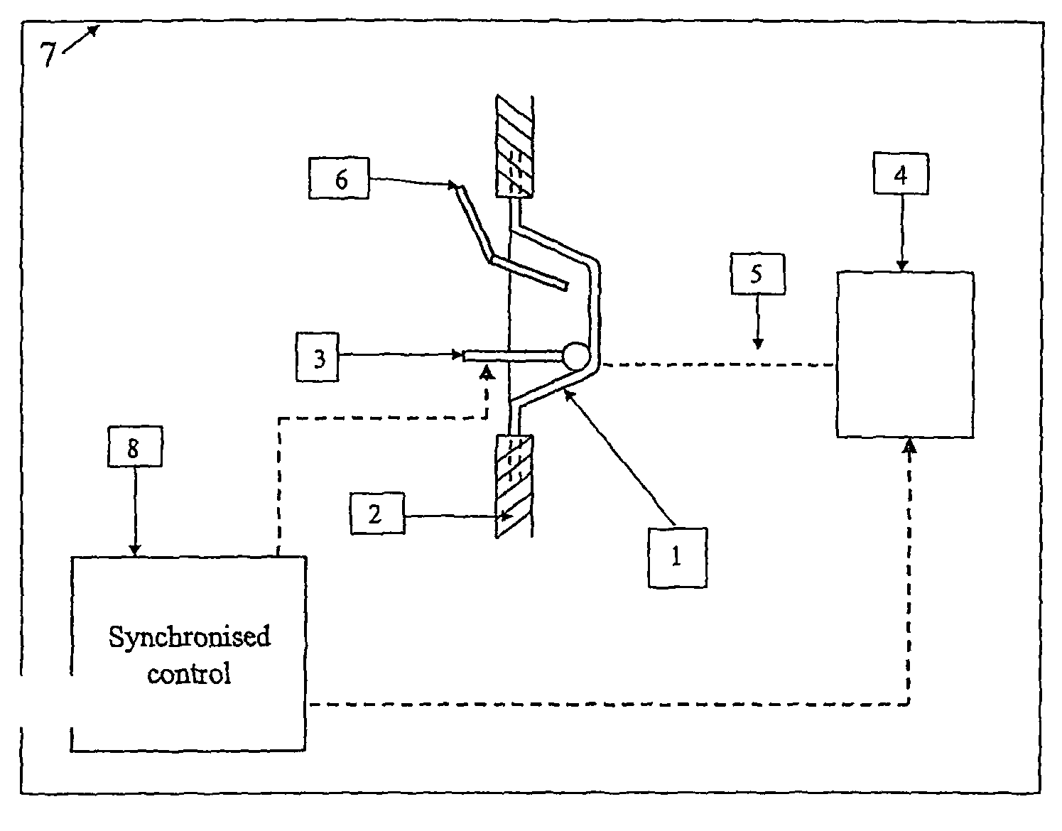
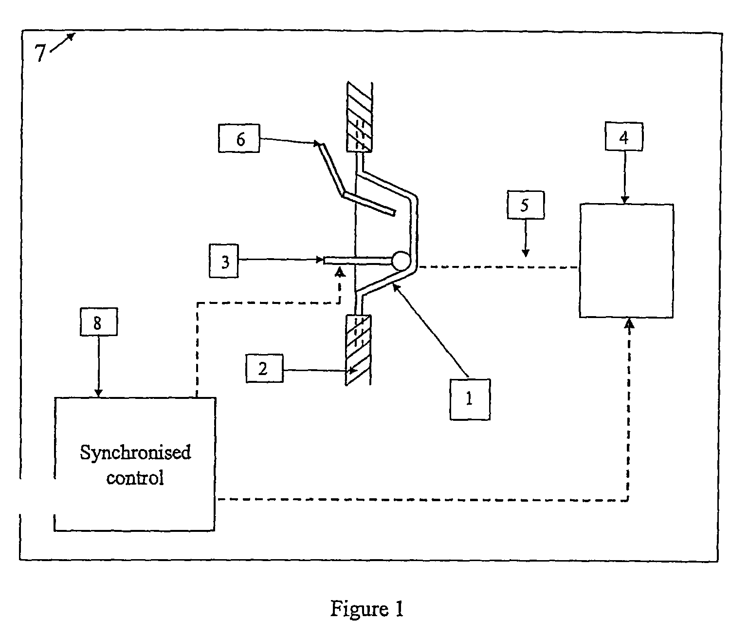
[0011]The invention concerns an asymmetric incremental sheet forming (AISF) apparatus comprising at least one clamping system (2) for holding a sheet material (1) and at least one forming tool (3) whereby the forming tool (3) and the sheet material are movable relatively towards each others in three dimensions to plastically deform contact points on to the sheet material (1) along defined toolpath corresponding to a defined three dimensional shape of the sheet material (1) to be formed and whereby the AISF apparatus is characterised by the inclusion of at least one heating means (4) arranged to locoregionally provide a heat flux (5) to the sheet material (1) and to increase the plasticity of the sheet material (1) along the contact toolpath of the forming tool (3).
[0012]The heating means (4) in this apparatus is located to provide a heat flux (5) that dynamically follows the moving contact zone of the toolpath of the forming tool (3) on the sheet material (1). Furthermore the heating means (4) can be arranged to locoregionally provide a heat flux (5) to the sheet material (1) and to increase the plasticity of the sheet material (1) on the tool path of the forming tool (3) at the contact zone of the forming tool (3) or slightly offset to the contact zone of the forming tool (3).
[0013]In a particular embodiment the heating means (4) is arranged to locoregionally provide a heat flux (5) to the sheet material (1) and to increase the plasticity of the sheet material (1) on the toolpath of the forming tool (3) with a lateral offset to the contact zone of the forming tool (3).
[0014]But alternatively the heating means (4) is arranged to locoregionally provide a heat flux (5) to the sheet material (1) and to increase the plasticity of the sheet material (1) on the toolpath of the forming tool (3) with a forward offset to the contact zone of the forming tool (3). A particular advantage of such apparatus is that it can be used to shape sheet materials in the desired forms with less formation of material strains and thus without the need of a separate annealing step.

Problems solved by technology

The method, however, has the drawback that the forces on the forming means become high when forming thicker material or material with high yield strength and low ductility.
For instance if the content of carbon rises in alloys of iron and carbon, the metal becomes harder and stronger but less ductile and it is more difficult to shape the alloy sheet with an asymmetric incremental sheet forming (AISF) apparatus.
Furthermore, it is generally not possible to substantially form harder and stronger but less ductile materials such as the alloys of iron and carbon for instance medium carbon steel: 0.29% to 0.54% (e.g. AISI 1040 steel), high carbon steel: 0.55% to 0.95%, very high carbon steel: 0.96% to 2.1% or the Titanium Grade 5 or Magnesium sheet materials.
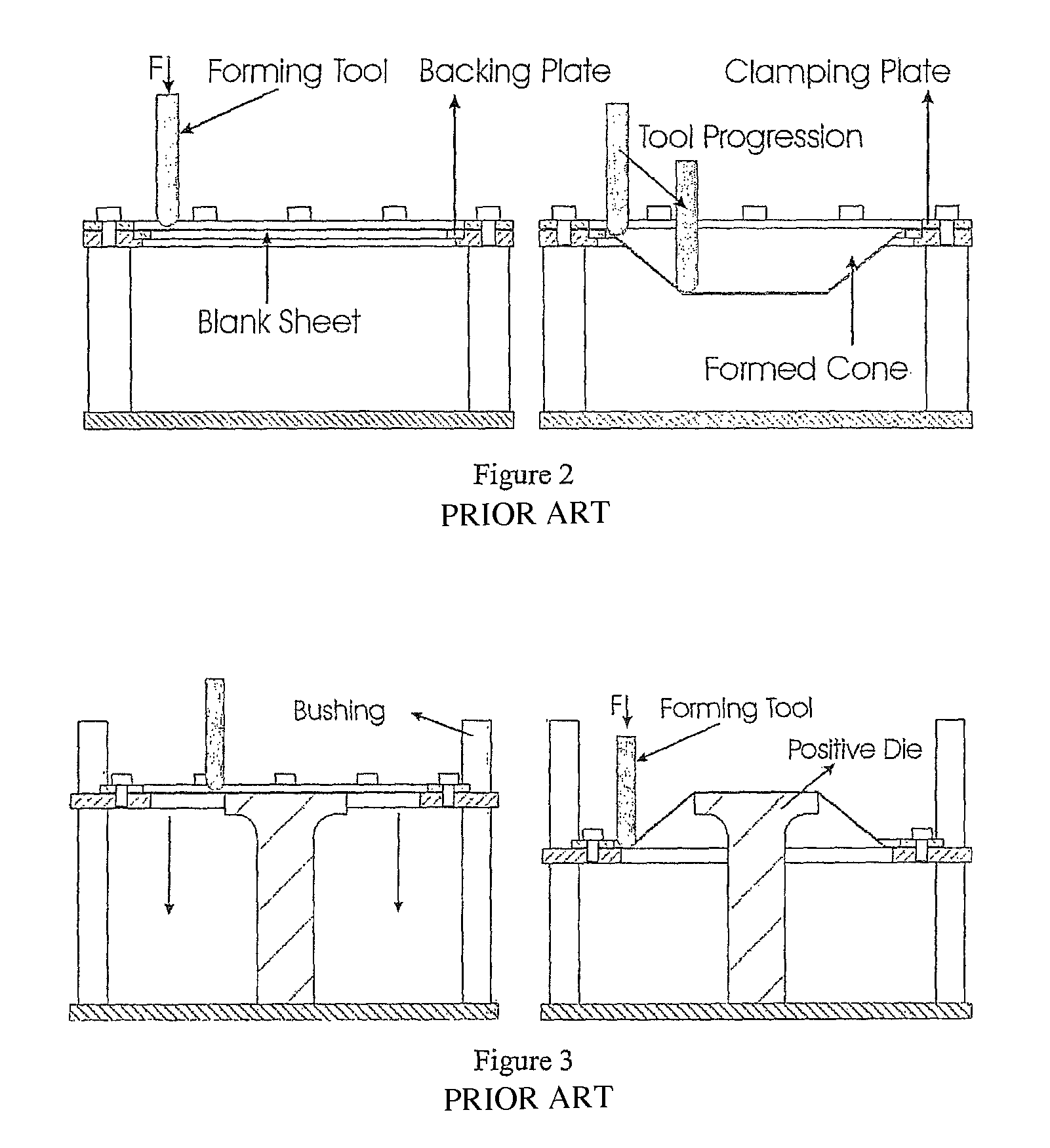
Yet another drawback is the difficulty to create clearly localised slope changes within parts.
These backing plates are cumbersome to work with and very difficult to use when the sudden slope change is not located near the edge of the plate.

Method used


Image

  • Asymmetric incremental sheet forming system
  • Asymmetric incremental sheet forming system
  • Asymmetric incremental sheet forming system

Examples


example 1

[0047]A sheet metal blank 1 of aluminium alloy EN 5182 (‘Innerlite’) of 1.15 mm thickness and a single point incremental forming means 3 of 10 mm diameter made out of tungsten carbide (‘grade Cki10’) and coated with a high temperature resistant coating, mounted on a 6-axis robot is used to form a pyramid with a wall angle of 40° using a step down of 0.5 mm. First, no heating was applied. and a feed rate of 1500 mm / min was used. In a second test, a Nd:YAG 500 W laser torch, mounted on a 3-axis XYZ-table, was used as the heat source 4 to provide the heat flux to the sheet material at the opposite side of the forming side. The effective laser power was 300 W, a spot size of 7 mm and a feed rate of both the laser and the forming tool of 1125 mm / min were used. The forward offset between the center of the heating and the center of the forming tool was 2.4 mm, while the lateral offset was zero. FIG. 4 gives a top view of the forming surface. The movement of the 9 axes was controlled using ...

example 2

[0048]A sheet metal blank 1 of Din65Cr2 (‘Blue sheet’) of 0.5 mm thickness with Rockwell hardness of about 60 at room temperature and with ultimate tensile strength in function of temperature as shown in FIG. 6 has been used to compare a cold with a heated single point incremental forming test. For the forming a forming means 3 made of tungsten carbide (‘grade Cki10’), coated with a high temperature resistant coating having a diameter of 10 mm and mounted on a 6-axes robot, CNC controlled, has been used to coldly form a conical shape with outer contour 160 mm, depth 40 mm and wall angle 57°. The step down size was 0.5 mm. For lubrication a graphite coating has been applied. The feedrate of the robot was set to 1500 mm / min. It was possible to make this part, whereas the part with wall angle 58° and the same settings as before cracked and thus failed. Therefore, with the settings, material and equipment as mentioned before, the conclusion is that for the cold forming the maximum obtai...

example 3

[0050]A sheet metal blank 1 of Din65Cr2 (‘Blue sheet’) of 0.5 mm thickness with Rockwell hardness of about 60 at room temperature and with ultimate tensile strength in function of temperature as shown in FIG. 6 was used to compare a cold with a heated single point incremental forming test. For the forming a forming means 3 made of tungsten carbide (‘grade Cki10’), coated with a high temperature resistant coating having a diameter of 10 mm and mounted on a 6-axes robot, CNC controlled, was used to coldly form a conical shape with outer contour 160 mm, depth 40 mm and wall angle 50°.

[0051]The step down size 0.5 mm. For lubrication a water-mixable high-performance cutting fluid based on a natural ester (vegetable ester based), known as Vasco 1000 was used. The feedrate of the robot was set to 1500 mm / min. The Din65Cr2 sample was clamped using a square backing plate that was at least 20 mm away from the slope change (i.e. the beginning of the cone). After forming, the sample stayed clam...


PUM

PropertyMeasurementUnit
diameteraaaaaaaaaa
diameteraaaaaaaaaa
diameteraaaaaaaaaa

Abstract

The present invention relates, in general, to sheet material forming technology and the forming of structures there from. The invention relates to incremental forming of sheet material (1) with localised heating (5) and more particularly to a system and method for incrementally forming a sheet blank (1) that is at the same time heated by a dynamically moving heating source (5). This dynamic and localised heating locally changes the mechanical properties of the sheet material (1), thus facilitating the forming process.

Description

BACKGROUND OF THE INVENTION[0001]A. Field of the Invention[0002]The present invention relates, in general, to an improvement of the Asymmetric Incremental Sheet Forming (AISF) technology, and more particularly to an improved Asymmetric Incremental Sheet Forming (AISF) apparatus or method for easier and more accurately forming of sheet material of various composition. More particularly the invention is related to a system and method for asymmetric incrementally forming a sheet material blank by means of a locoregional heat / cooling system that is synchronised with the movement of the forming tool. The sheet material is at the same time locally heated at the contact zone of the forming means by a dynamically moving heating source that moves synchronically with the movement of the forming means over the surface of the sheet material to locally increase plasticity of the sheet material only at the contact zone of the forming tool or just in front or next to the contact zone of the formin...

Claims


Application Information

Patent Timeline
Patent Type & Authority Patents(United States)
IPC IPC(8): B21D37/16
CPCB21D31/005
Inventor CALLEBAUT, BARTDUFLOU, JOOSTVERBERT, JOHAN
Owner K U LEUVEN RES & DEV
Learn More