External cavity wavelength tunable laser device and optical output module

a laser device and optical output technology, applied in semiconductor lasers, laser details, optical resonator shape and construction, etc., can solve the problems of increasing the cost of inventory management and stocktaking, increasing the loss of optical couplers, and external cavity wavelength tunable lasers, so as to minimize the loss in the external cavity, high laser mode stability, and high optical power operation

Inactive Publication Date: 2011-08-02
NEC CORP
View PDF16 Cites 7 Cited by
  • Summary
  • Abstract
  • Description
  • Claims
  • Application Information

AI Technical Summary

Benefits of technology

[0032]According to the present invention, in the external cavity wavelength tunable laser device comprising the external cavity which includes the semiconductor optical amplifier and performs laser oscillation operation by feeding back external light, the wavelength tunable mirror having at least a single-peak reflection spectrum characteristic within the laser wavelength tuning range is placed on one end of the external cavity, and the Fabry-Perot mode interval determined by the effective length of the external cavity is not less than 1 / 10 times and not more than 10 times the reflection band full width half maximum of the wavelength tunable mirror. With this arrangement, the following effects can be obtained. The first effect is that an external cavity wavelength tunable laser device which has high laser mode stability and performs high optical power operation can be implemented. This is because this arrangement is configured to minimize loss in the external cavity and give consideration to the laser mode. As compared with the same optical power of the conventional external cavity wavelength tunable laser device, a reduction in driving current can be achieved. The second effect is that this device can obtain the same high wavelength accuracy as that obtained by a distributed feedback semiconductor laser having a wavelength locker mounted outside a laser cavity. This is because the present invention also allows a wavelength locker to be mounted outside the laser cavity. The third effect is that high frequency modulation (FM modulation) efficiency can be obtained. This is because no narrow-band filter like a wavelength selection filter is used to facilitate FM modulation. This makes it possible to suppress stimulated Brillouin scattering in an optical fiber and implement long-distance communication. The fourth effect is that this device can continuously change the laser oscillation wavelength, and can easily cope with a case in which the channel intervals for wavelength division multiplexing communication decrease in the future. The fifth effect is that the number of laser parts can be reduced, and the phase adjustment mechanism can be simplified, thereby implementing a low-cost, easily controllable wavelength tunable laser. In addition, obviating the necessity of phase adjustment can increase wavelength switching speed. With the above first to fifth effects, the present invention can implement a low-cost external cavity wavelength tunable laser device suitable for long-distance communication which suppresses power consumption, and achieves high channel wavelength accuracy.
[0033]In addition, according to the present invention, in the external cavity wavelength tunable laser device comprising the external cavity which includes the semiconductor optical amplifier and the total reflection mirror which performs laser oscillation operation by feeding back external light, the wavelength tunable filter having at least a single-peak transmission spectrum characteristic within the laser wavelength tuning range is placed between the semiconductor optical amplifier and the total reflection mirror, and the Fabry-Perot mode interval determined by an effective length of the external cavity is not less than 1 / 10 times and not more than 10 times the transmission band full width half maximum of the wavelength tunable filter. With this arrangement, the first to fifth effects can be obtained.

Problems solved by technology

Because of this arises a problem of increasing the cost of inventory management and stocktaking.
If, therefore, the number of DFB lasers arranged in parallel increases, the loss in the optical coupler increases.
However, the external cavity wavelength tunable lasers disclosed in references 5 and 8 also include several problems.
The first problem is that such an arrangement is not suitable for the implementation of a high power laser.
This is because, since the wavelength selection filter is inserted between the semiconductor optical amplifier and the total reflection mirror, optical loss occurs when light is transmitted through the wavelength selection filter, resulting in interference with an increase in the power of the laser.
That is, when light with other wavelengths strike the etalon, the optical power is partly or totally reflected due to interference.
On the other hand, when an optical power component which is not transmitted through the etalon is reflected by the etalon and returns to the semiconductor optical amplifier, the light interferes with the laser oscillation mode stability.
This causes excessive optical loss for the external cavity, and hence hinders an increase in laser power.
The second problem in the conventional external cavity wavelength tunable laser is that some limitation is imposed on wavelength accuracy obtained with respect to the standard channel wavelength.
However, since the change amount of optical power is small near the transmission peak of the wavelength selection filter, it is difficult to make the laser oscillation wavelength perfectly coincide with the transmission peak of the wavelength selection filter by the above control operation of maximizing optical power.
That is, a certain degree of error is unavoidable.
Therefore, in comparison with the structure having the wavelength lock mechanism added to the outside of the laser cavity disclosed in reference 2, some limitation is imposed on wavelength accuracy with respect to the standard channel.
The third problem in the conventional external cavity wavelength tunable laser is that the frequency modulation (FM modulation) efficiency is low.
If, however, a wavelength selection filter is used, the FM modulation efficiency decreases, and SBS cannot be suppressed, resulting in an increase in loss in the optical fiber.
This poses a problem in long-distance communication.
The fourth problem of the conventional external cavity wavelength tunable laser is that continuous wavelength tuning operation cannot be performed.
The fifth problem of the conventional external cavity wavelength tunable laser is that the cost is high.
This means that the optical arrangement of the external cavity wavelength tunable laser and its control circuit arrangement become complicated.
This becomes a factor that increases the cost and decreases the wavelength switching speed.

Method used


Image

  • External cavity wavelength tunable laser device and optical output module
  • External cavity wavelength tunable laser device and optical output module
  • External cavity wavelength tunable laser device and optical output module

Examples


first embodiment

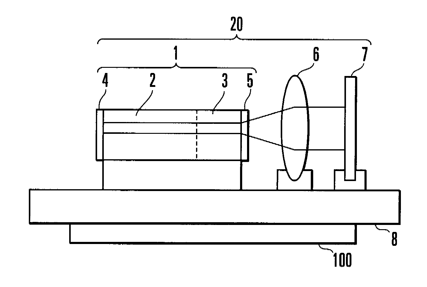
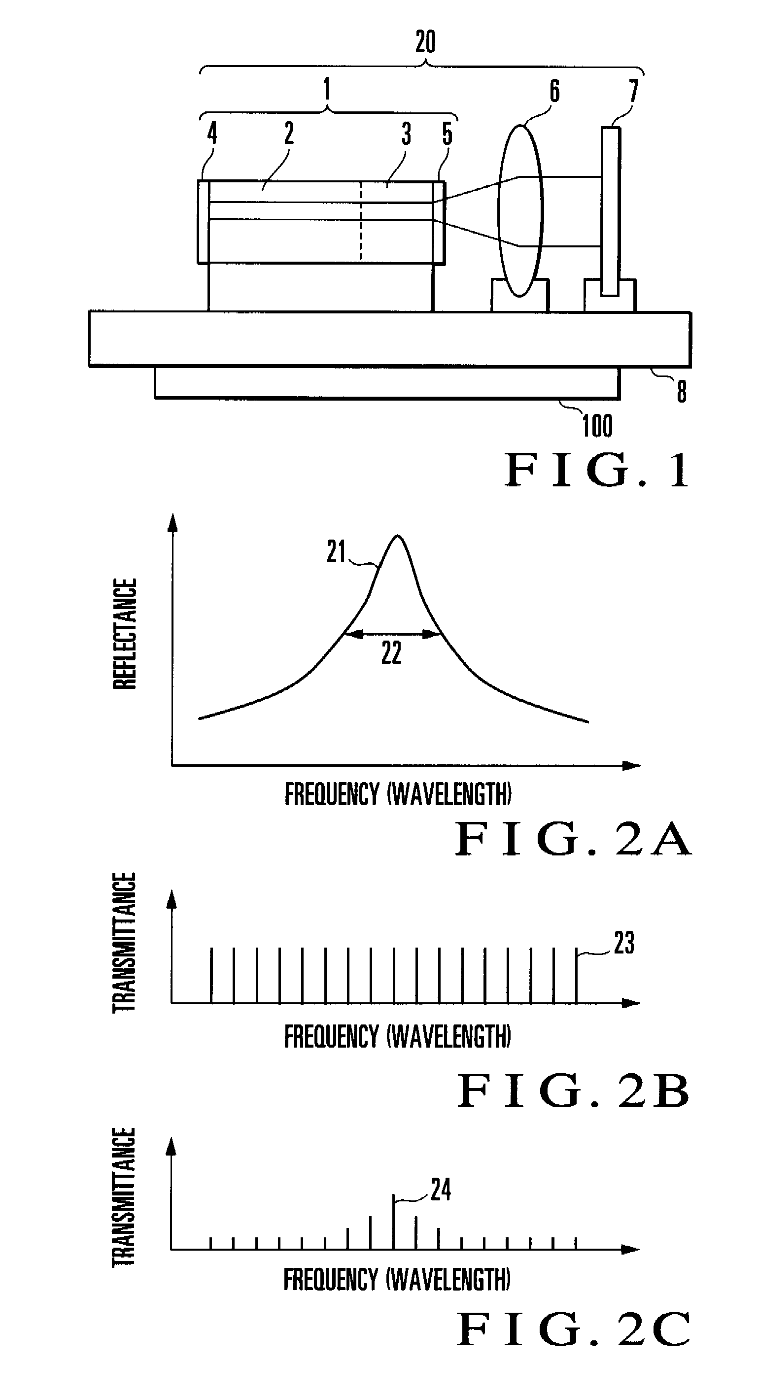
[0061]The embodiments of the present invention will be described below with reference to the accompanying drawings. FIG. 1 is a side view showing the arrangement of an external cavity wavelength tunable laser according to the first embodiment of the present invention. This embodiment is configured not to use any wavelength selection filter in order to prevent optical loss due the use of a wavelength selection filter. An external cavity wavelength tunable laser according to this embodiment comprises a semiconductor element 1 including a semiconductor optical amplifier 2, a collimating lens 6, and a wavelength tunable mirror 7 whose reflection characteristic within the operating wavelength band is not periodic.

[0062]The semiconductor element 1 is obtained by integrating a phase adjustment area 3 as a passive element with the semiconductor optical amplifier 2 as an active element. In this embodiment, laser light is output from the left end face of the semiconductor optical amplifier 2....

second embodiment

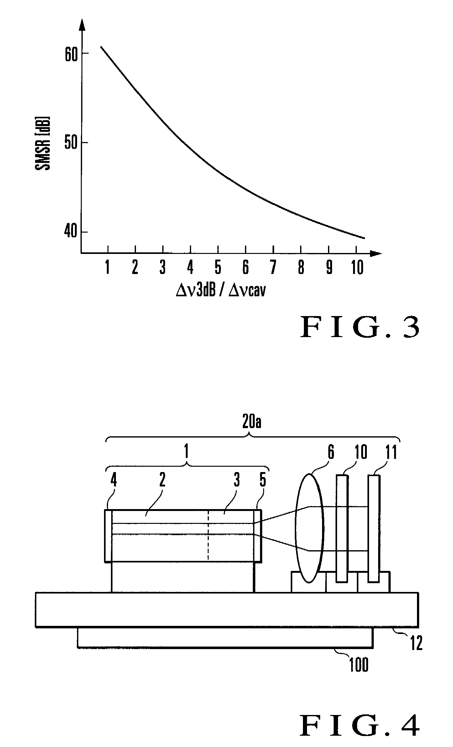
[0081]The second embodiment of the present invention will be described next. FIG. 4 is a side view showing the arrangement of an external cavity wavelength tunable laser according to the second embodiment of the present invention. The same reference numerals as in FIG. 1 denote the same components in FIG. 4. The external cavity wavelength tunable laser of this embodiment comprises a semiconductor element 1 including a semiconductor optical amplifier 2, a collimating lens 6, a wavelength tunable filter 10 whose transmission characteristic within the operating wavelength band is not periodic, and a total reflection mirror 11.

[0082]This embodiment uses the wavelength tunable filter 10 and the total reflection mirror 11 instead of the wavelength tunable mirror 7 in the first embodiment. That is, an external cavity 20a comprises a low-reflection coating 4, the semiconductor optical amplifier 2, a phase adjustment area 3, a nonreflective coating 5, the collimating lens 6, the wavelength t...

third embodiment

[0093]The third embodiment of the present invention will be described next. FIG. 6 is a side view showing the arrangement of an external cavity wavelength tunable laser according to the third embodiment of the present invention. The same reference numerals as in FIG. 1 denote the same components in FIG. 6. In the first embodiment, the known wavelength locker mechanism disclosed in reference 2 can be placed outside the laser cavity. This can improve the wavelength accuracy with respect to the standard channel wavelength. In the third embodiment, the external cavity wavelength tunable laser of the first embodiment is incorporated in a module, and a wavelength locker is placed on the optical output side.

[0094]Referring to FIG. 6, reference numeral 1 denotes a semiconductor element; 2, a semiconductor optical amplifier; 3, a phase adjustment area; 7, a wavelength tunable mirror; 20, an external cavity; 31, an external cavity wavelength tunable laser module; 32, a first collimating lens ...


PUM


Abstract

In an external cavity wavelength tunable laser device including an external cavity (20) which includes a semiconductor optical amplifier (2) and performs laser oscillation operation by feeding back external light, a wavelength tunable mirror (7) having at least a single-peak reflection spectrum characteristic within a laser wavelength tuning range is placed on one end of the external cavity (20), and a Fabry-Perot mode interval determined by the effective length of the external cavity (20) is not less than 1 / 10 times and not more than 10 times the reflection band full width half maximum of the wavelength tunable mirror (7).

Description

TECHNICAL FIELD[0001]The present invention relates to a mechanism for selecting a desired laser oscillation wavelength in a wavelength division multiplexing optical communication system and, more particularly, to a wavelength tunable laser device having an external cavity structure using a tunable filter and an optical output module including an external cavity wavelength tunable laser device.BACKGROUND ART[0002]Recently, with the rapid proliferation of the Internet, there has been a demand for a further increase in communication traffic. Under the circumstance, the transmission rate per unit channel in a system has increased as well as the number of channels based on wavelength division multiplexing (to be abbreviated as WDM hereinafter). WDM is a scheme which can simultaneously transmit a plurality of optical signals assigned to different carrier wavelengths (channels), and allows an increase in communication capacity in accordance with the number of channels. The respective chann...

Claims


Application Information

Patent Timeline
Patent Type & Authority Patents(United States)
IPC IPC(8): H01S3/13H01S3/08
CPCH01S5/141
Inventor SATO, KENJIDE MERLI, JANMIZUTANI, KENJIKUDO, KOJISUDO, SHINYANIELSEN, MADS. L
Owner NEC CORP
Why Eureka
Try Eureka