Electrically conductive thin film formed from an ionic liquid and carbon nanotubes having a high aspect ratio, and actuator element comprising the thin film

a technology of carbon nanotubes and ionic liquid, which is applied in the direction of generators/motors, capacitors, coatings, etc., can solve the problems of difficult uniform mixing of polymers, ionic liquid, and actuators obtained cannot exhibit desired high performance, and prevent the uniform distribution of carbon nanotubes in the film. , to achieve the effect of improving the response speed, reducing the deformation of the element, and improving the electronic conductivity and ion conductivity

Inactive Publication Date: 2011-08-23
NAT INST OF ADVANCED IND SCI & TECH
View PDF9 Cites 10 Cited by
  • Summary
  • Abstract
  • Description
  • Claims
  • Application Information

AI Technical Summary

Benefits of technology

[0027]The present invention makes it possible to obtain an electrically conductive thin film without adding a polymer. This improves response speed, electronic conductivity and ion conductivity, and lightens the element or eases deformation of the element. Accordingly, the present invention provides an actuator element that is deformable and highly efficient.BRIEF DESCRIPTION OF SEVERAL VIEWS OF THE DRAWINGS
[0028]FIG. 1 shows a laser displacement meter used for evaluation of the displacement of the actuator element in the Examples of the present invention.
[0029]FIG. 2 (A) shows a schematic diagram of an example of the actuator element (three-layer structure) of the present invention, and FIG. 2 (B) shows a schematic diagram of an example of the actuator element (five-layer structure) of the present invention.
[0030]FIG. 3 shows the operation principle of the actuator element of the present invention.
[0031]FIG. 4 shows a schematic diagram of another example of the actuator element according to the invention.
[0032]FIG. 5 is photographs of the appearance of an electrode film. The right- and left-side photographs show front and rear side of the film.

Problems solved by technology

According to the known processes for producing actuator elements, it is difficult to uniformly mix polymer, ionic liquid, and carbon nanotube having the above excellent properties.
As a result, the actuator obtained cannot exhibit desired high performance.
The addition of a polymer, however, prevents uniform distribution of the carbon nanotubes in the film, and leads to lowered electronic and ionic conductions.Patent Document 1: Japanese Unexamined Patent Application Publication No. 2005-176428

Method used


Image

  • Electrically conductive thin film formed from an ionic liquid and carbon nanotubes having a high aspect ratio, and actuator element comprising the thin film
  • Electrically conductive thin film formed from an ionic liquid and carbon nanotubes having a high aspect ratio, and actuator element comprising the thin film
  • Electrically conductive thin film formed from an ionic liquid and carbon nanotubes having a high aspect ratio, and actuator element comprising the thin film

Examples


example 1

[0087]LS-CNT (5 mg) and EMIBF4 (40 mg) were introduced into a bottle, 1 ml of DMAc as a solvent was added thereto, and the whole material was agitated for 1 hour using a magnetic stirrer. The resulting mixture was solidified to an extent that it did not flow even when the bottle was turned upside-down. It is assumed that the LS-CNT uniformly dispersed in the mixture to form a network and turned the mixture into a gel-like solid. The obtained solid was then irradiated with ultrasonic waves in an ultrasonic cleaner for 30 minutes, and 2 ml of DMAc was added thereto. Thereafter, it was agitated for 2 hours with a stirrer, and a liquid for casting was thereby obtained. A 2.4 ml quantity of the obtained casting liquid was poured into a 25 mm×25 mm cast frame made of PTFE (Teflon: registered trademark) tape. Each casting liquid in each cast frame was dried under reduced pressure at a temperature of 50° C. for 24 hours. Then, the temperature was adjusted to 80° C., and the cast product was...

example 2

[0089]LS-CNT (5 mg) and EMIBF4 (40 mg) were introduced into a bottle, 1 ml of DMAc as a solvent was added thereto, and the whole material was agitated for 1 hour using a magnetic stirrer. The resulting mixture was solidified to an extent that it did not flow even when the bottle was turned upside-down. It is assumed that the LS-CNT uniformly dispersed in the mixture to form a network and turned the mixture into a gel-like solid. The obtained solid was then irradiated with ultrasonic waves in an ultrasonic cleaner for 1 hour, and 2 ml of DMAc was added thereto. Thereafter, it was agitated for 2 hours with a stirrer, and a liquid for casting was thereby obtained. A 2.4 ml quantity of the obtained casting liquid was poured into a 25 mm×25 mm cast frame made of PTFE (Teflon: registered trademark) tape. Each casting liquid in each cast frame was dried under reduced pressure at a temperature of 50° C. for 24 hours. Then, the temperature was adjusted to 80° C., and the cast product was dri...

example 3

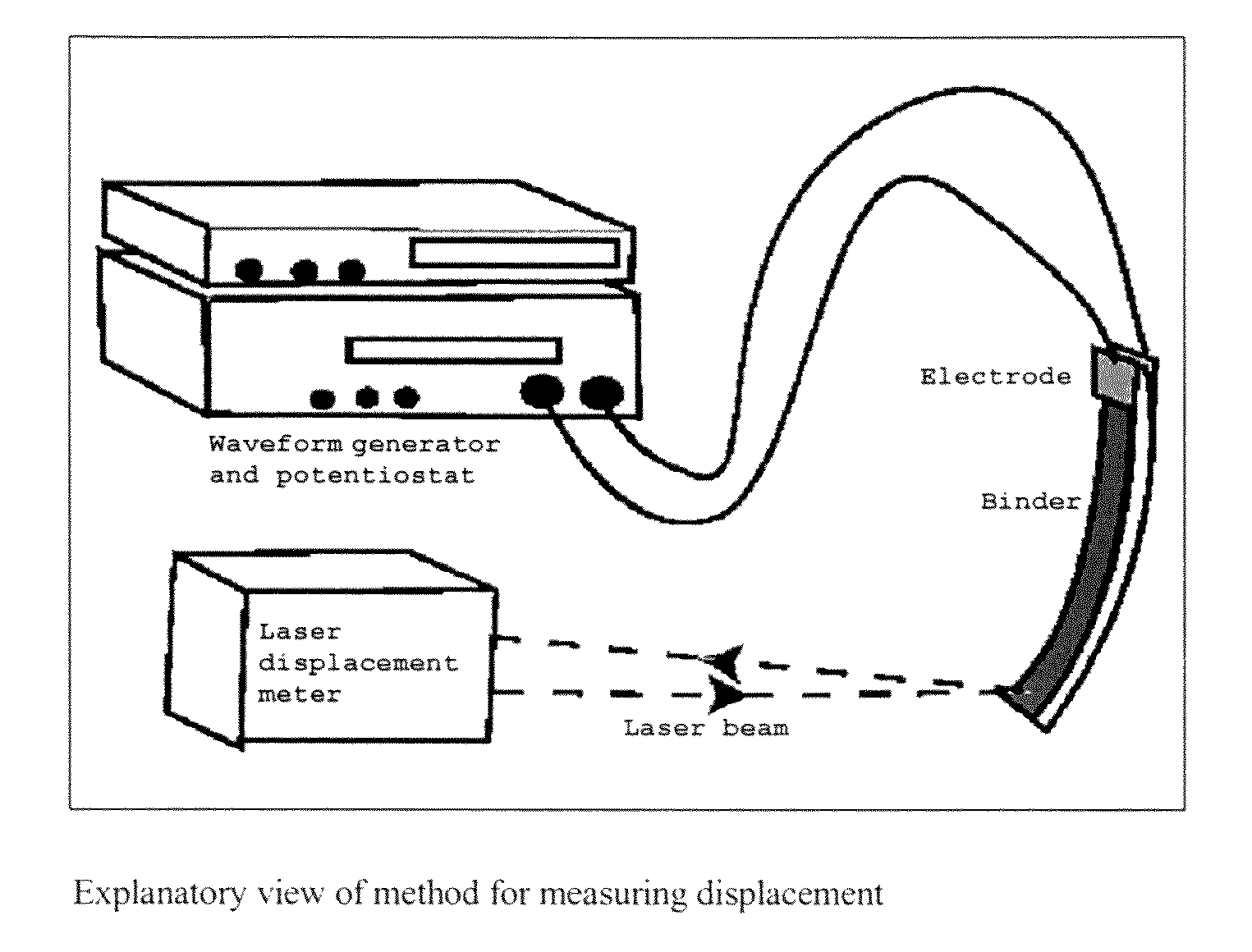
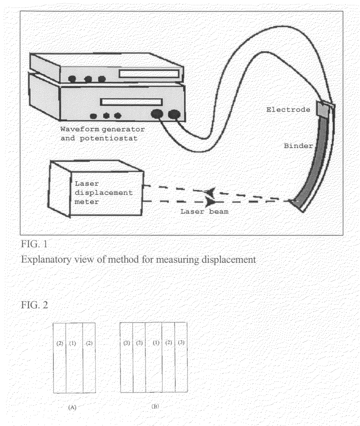
[0092]Each gel electrolyte layer produced in accordance with the common experimental procedure 3 was sandwiched between the two electrode films produced in Examples 1 and 2, respectively, and was pressed for 1 minute at 70° C. under a pressure of 1.9 N / mm2. Thereby, each electrode / electrolyte / electrode composite (actuator element) was obtained. Table 3 summarizes displacements observed when square wave voltages of ±2.5 V having various frequencies were applied across the electrodes. Even at a frequency of 5 Hz, a displacement of not less than 1 mm was observed. The result shows that the thus-obtained actuator element exhibits high-speed response.

[0093]

TABLE 3Displacement response of the element obtained in Example 3Voltage frequency (Hz)0.010.1125Electrode of2.081.801.231.100.94Example 1 (mm)Electrode of2.622.031.841.641.50Example 2 (mm)

(Thickness of each actuator element:[0094]the element comprising the electrodes of Example 1: 85 μm, and the element comprising the electrodes of Ex...


PUM

PropertyMeasurementUnit
aspect ratioaaaaaaaaaa
lengthaaaaaaaaaa
temperatureaaaaaaaaaa

Abstract

The present invention provides an actuator exhibiting improved performance. The actuator is formed of an electrically conductive thin film formed from an ionic liquid and carbon nanotubes having an aspect ratio of not less than 104; or an electrically conductive thin film formed from an ionic liquid and carbon nanotubes having a length of not less than 50 μm.

Description

BACKGROUND OF THE INVENTION[0001](1) Field of the Invention[0002]The present invention relates to an electric conductor having an electrically conductive thin film, an actuator element using the electric conductor, and a method for producing the actuator. The actuator element of the invention is driven by an electrochemical process such as an electrochemical reaction, the charging and discharging of an electric double layer.[0003](2) Description of the Related Art[0004]Patent Document 1 discloses an actuator element; the actuator comprises, as an active layer exhibiting conductivity and flexibility, a gel containing carbon nanotubes and an ionic liquid, and is capable of operating in air or in a vacuum.[0005]Carbon nanotubes used as electric conductors are required to have excellent properties, such as high purity, high aspect ratio, high electric conductivity, and high specific surface area.[0006]According to the known processes for producing actuator elements, it is difficult to u...

Claims


Application Information

Patent Timeline
Patent Type & Authority Patents(United States)
IPC IPC(8): H01L41/08B81C99/00H02N11/00
CPCB81B3/0021H02N11/006
Inventor ASAKA, KINJIMUKAI, KENHATA, KENJI
Owner NAT INST OF ADVANCED IND SCI & TECH
Why Eureka
Try Eureka