Time-of-flight measuring device

a measuring device and time-of-flight technology, applied in the field of time-of-flight measuring devices, can solve the problems of large amount of data, impractical infinitely raising sampling frequency, and requiring a larger capacity of data storage devices, so as to shorten the period of time for transferring data, improve the processing performance of the device, and compress data at high speeds

Inactive Publication Date: 2011-08-23
SHIMADZU CORP
View PDF14 Cites 26 Cited by
  • Summary
  • Abstract
  • Description
  • Claims
  • Application Information

AI Technical Summary

Benefits of technology

[0057]The time-of-flight measuring device according to the present invention can compress data at high speeds by means of a hardware device in a signal recorder. This shortens the period of time for transferring data to a data processor, such as a computer, and improves the processing performance of the device. Compressing the data also decreases the amount of use of an external storage device, such as a hard disk, and thereby reduces the frequency of creating backup data on a DVD or other media. The signal recorder can be operated at higher sampling frequency to record signals, whereby the resolution can be enhanced to improve the device performance. In the case of a time-of-flight mass spectrometer, its mass-resolving power will be improved.

Problems solved by technology

Therefore, it is impractical to infinitely raise the sampling frequency; the sampling frequency needs to be selected so that the amount of data will be appropriately reduced according to the data-processing speed.
Furthermore, it also requires a larger capacity of data storage devices, such as hard disk drives (HDD), for storing data in the data processor.
A major reason for the difficulty in increasing the sampling frequency is the increase in the data amount.
Although this level of data transfer rate can be achieved by using a gigabit Ethernet®, it will increase the load on the data processor and particularly cause a heavy load on the real-time data processing.
Furthermore, continuing the measurement produces 28.8 gigabytes of data for every one hour, which can easily exhaust the hard-disk capacity.
To prevent this situation, it is necessary to frequently transfer the data to external record media, such as digital versatile disks (DVDs), which further increases the load on the data processor.
In summary, the attempt to improve the analysis performance by simply raising the sampling frequency will produce an extremely large amount of data that cannot be handled at the processing speed of the entire system.
However, once these processes are completed, it is impossible to find minor mass peaks obscured by the noise even if an attempt is made to improve the signal-to-noise (S / N) ratio by integrating a plurality of mass spectrums in a post-processing or other stages.

Method used


Image

  • Time-of-flight measuring device
  • Time-of-flight measuring device
  • Time-of-flight measuring device

Examples


Embodiment Construction

[0080]As one example of the time-of-flight measuring device according to the present invention, a time-of-flight mass spectrometer is hereinafter described.

[0081]FIG. 7 is a configuration diagram showing the main components of a high performance liquid chromatograph ion trap time-of-flight mass spectrometer (LC-IT-TOFMS) using a high performance liquid chromatograph (LC) as a preprocessor for mass analysis. A liquid sample is injected into the LC 1 and exits the LC 1 at different points in time due to the properties of its components.

[0082]The liquid sample that serially exits the LC 1 with the elapse of time is subsequently ionized by an ion-introducing optical system 2 and introduced into a vacuum. The ion-introducing optical system 2 includes an ionization probe and an ion guide.

[0083]For example, the ionization is performed by using an electrospray ionization probe or atmospheric pressure chemical ionization probe (both not shown), which produces ions by atomizing the liquid sam...


PUM


Abstract

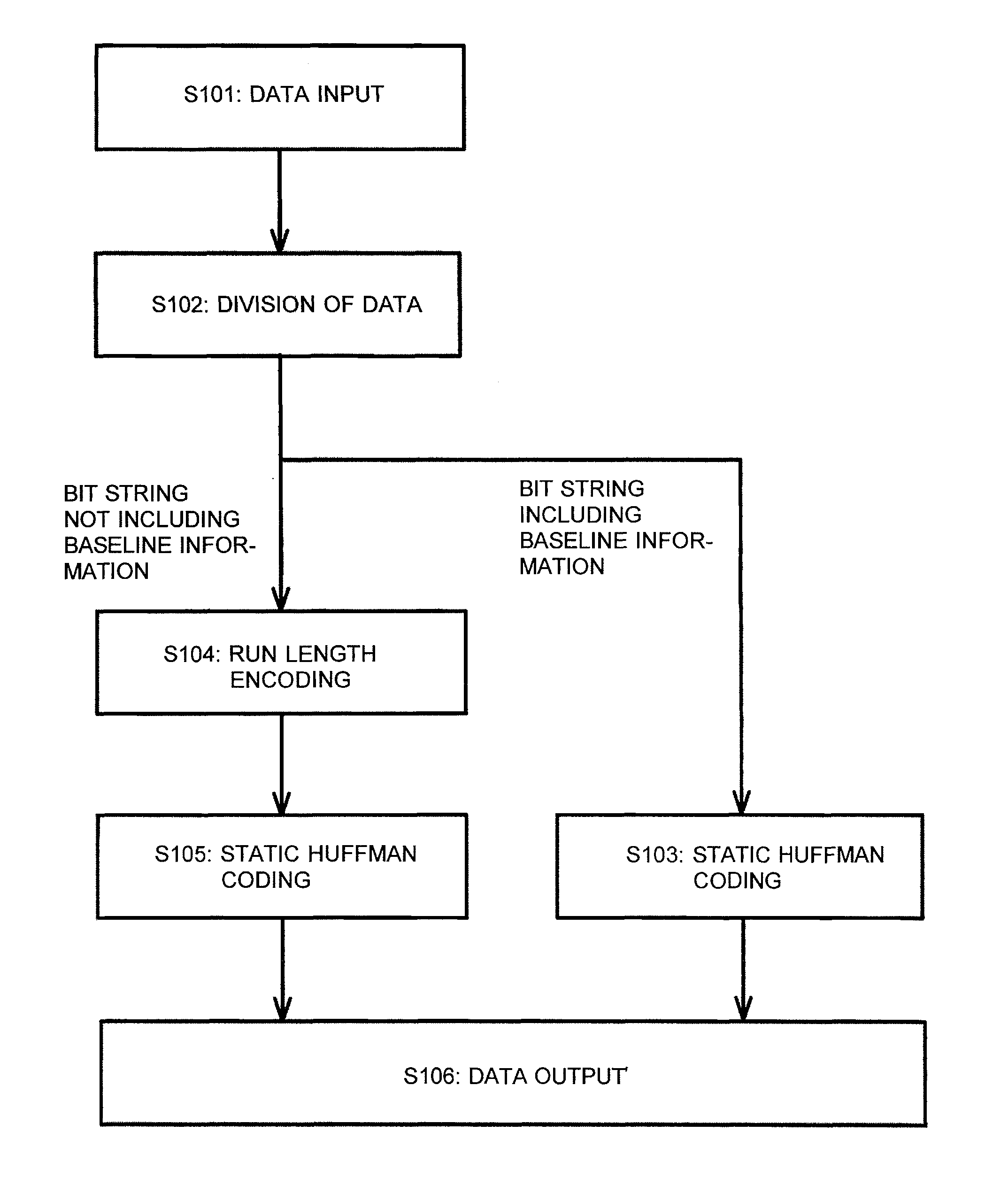
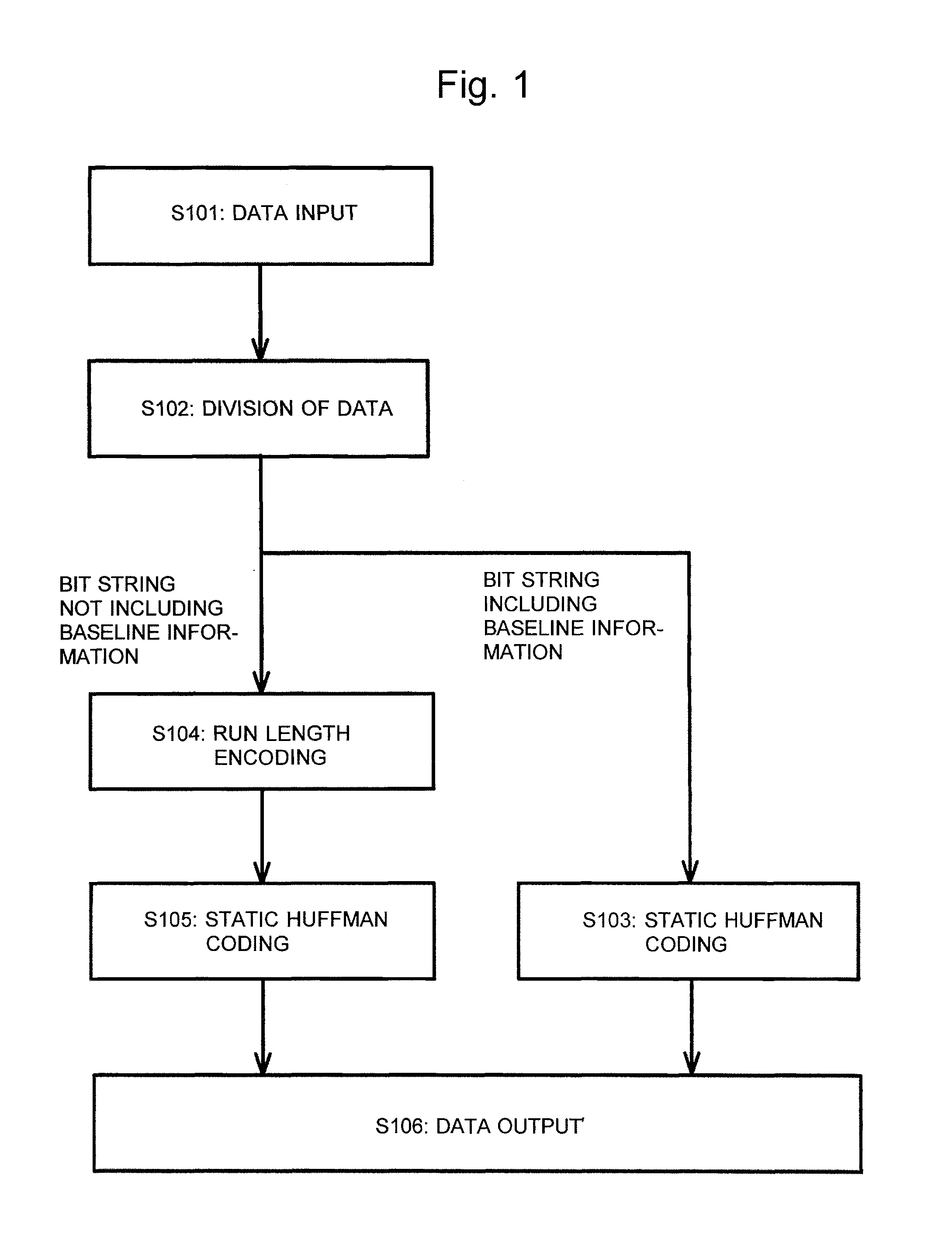
A time-of-flight measuring device for performing a hardware-based high-speed data compression process before transferring the data from a signal recorder to a data processor is provided. A time-series digital signal recorded by a signal recorder is converted to a plurality of time-series digital signals by being divided into a bit string including baseline information and a bit string not including the baseline information. Then, the time-series digital signal consisting of a bit string not including the baseline information is compressed by run-length encoding, such as zero length encoding or switched run-length encoding. Subsequently, static Huffman coding is performed on each of the time-series digital signals to reduce the data amount.

Description

CROSS REFERENCE TO RELATED APPLICATIONS[0001]This application is a National Stage of International Application No. PCT / JP2007 / 073179 filed Nov. 30, 2007, the content of which is incorporated herein by reference in its entirety.TECHNICAL FIELD[0002]The present invention relates to a time-of-flight measuring device having a signal recorder for recording a detection signal produced by a detector and for transferring data to a data processor.BACKGROUND ART[0003]The time-of-flight measuring device is a device for determining the energy of an ion or electron by measuring the time of flight of the charged particle. One variation of this device is an analyzing device called the time-of-flight mass spectrometer. In this device, an ion generated by an ion generator is accelerated to a specific speed and released into a flight space having a specific distance. Within this space, the ion is guided to fly to an ion detector, which produces a signal upon receiving the ion. The period of time from...

Claims


Application Information

Patent Timeline
Patent Type & Authority Patents(United States)
IPC IPC(8): H03M7/30
CPCH01J49/0036H01J49/40
Inventor KAWATO, EIZO
Owner SHIMADZU CORP
Why Eureka
Try Eureka