Recycle TSA regen gas to boiler for oxyfuel operations

a technology of oxyfuel and regen gas, which is applied in the direction of metal/metal-oxide/metal-hydroxide catalyst, indirect carbon-dioxide mitigation, liquefaction, etc., can solve the problems of high combustion temperature, which is not practical in a furnace or boiler, and achieves the effect of prolonging the life of an oxidation catalyst and efficient design

Inactive Publication Date: 2011-09-06
AIR PROD & CHEM INC
View PDF17 Cites 54 Cited by
  • Summary
  • Abstract
  • Description
  • Claims
  • Application Information

AI Technical Summary

Benefits of technology

[0024]A further object of preferred embodiments is to enable a more efficient design of integrated NOx and SOx removal systems.
[0025]It is a still further object of preferred embodiments to prolong the life of an oxidation catalyst within the adsorbent beds of a selective adsorbent system for removing at least NO2 from the carbon dioxide gas.
[0031]The method removes at least NO2 and, where water is present, at least substantially all of the water from the carbon dioxide gas. In addition, the adsorbent materials of the adsorbent system can be chosen and / or the adsorbent system designed such that, where present as further contaminants, NO, N2O, SOx and CO are also removed. Further, adsorption of NOx and / or SOx from the carbon dioxide gas enables control of the emission levels of these contaminants. Furthermore, where the NO2-enriched gas is recycled to an integrated oxyfuel combustion system, NOx may be destroyed in the boiler and, where SOx is present in the recycled stream, SOx concentration in the flue gas leaving the boiler will be increased thereby facilitating SOx removal downstream of the boiler. Also, in these embodiments, NOx and SOx removal systems may be more efficiently designed since any losses from the systems are simply recycled. In addition, where O2 is present in the carbon dioxide-rich gas, and the adsorbent beds of the selective adsorption system contain an oxidation catalyst, the O2 regenerates at least a portion of the catalyst, thereby prolonging the life of the catalyst.

Problems solved by technology

This process would result in an absence of nitrogen (N2) in the flue gas, together with a very high combustion temperature which would not be practical in a furnace or boiler.

Method used


Image

  • Recycle TSA regen gas to boiler for oxyfuel operations
  • Recycle TSA regen gas to boiler for oxyfuel operations
  • Recycle TSA regen gas to boiler for oxyfuel operations

Examples


example

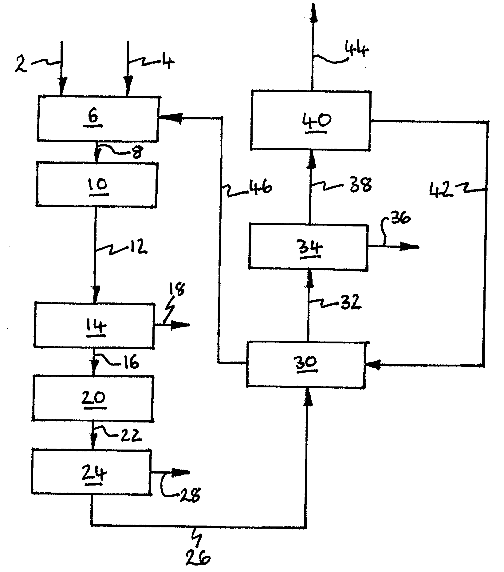
[0200]Computer simulations using the APSEN™ Plus software have also been carried out in respect of the embodiment of the present invention depicted in FIG. 5 which is a modified version of process depicted in FIG. 4.

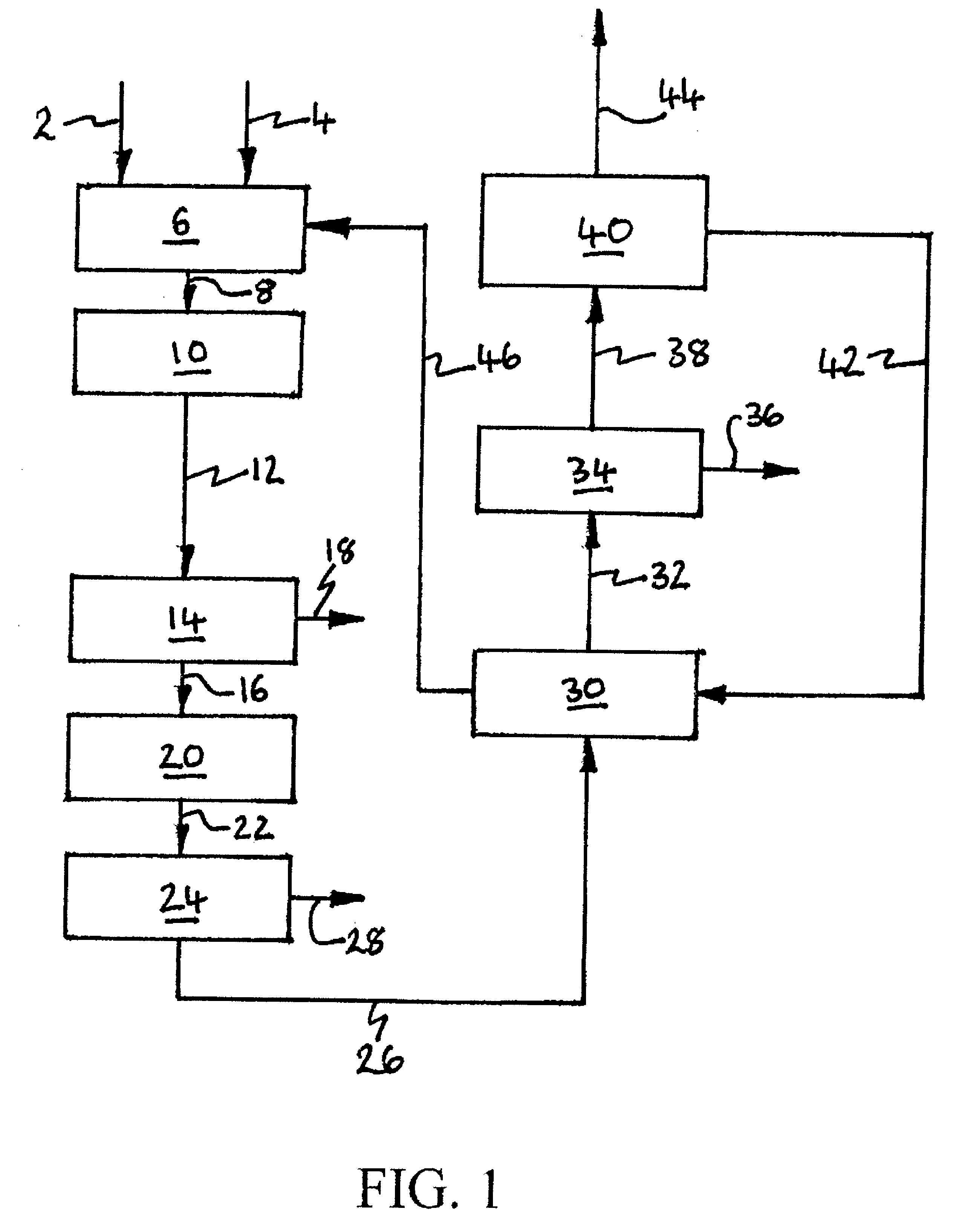
[0201]In this connection, a first simulation has been carried out in which the adsorption unit C103 contains extra layers of adsorbent material for removing NO2 and N2O. In addition, carbon dioxide-rich stream 42 from the carbon dioxide recovery system 40 is used to regenerate the adsorption system 30, rather than the stream 70 of expanded carbon dioxide-depleted gas comprising the non-condensable gas(es).

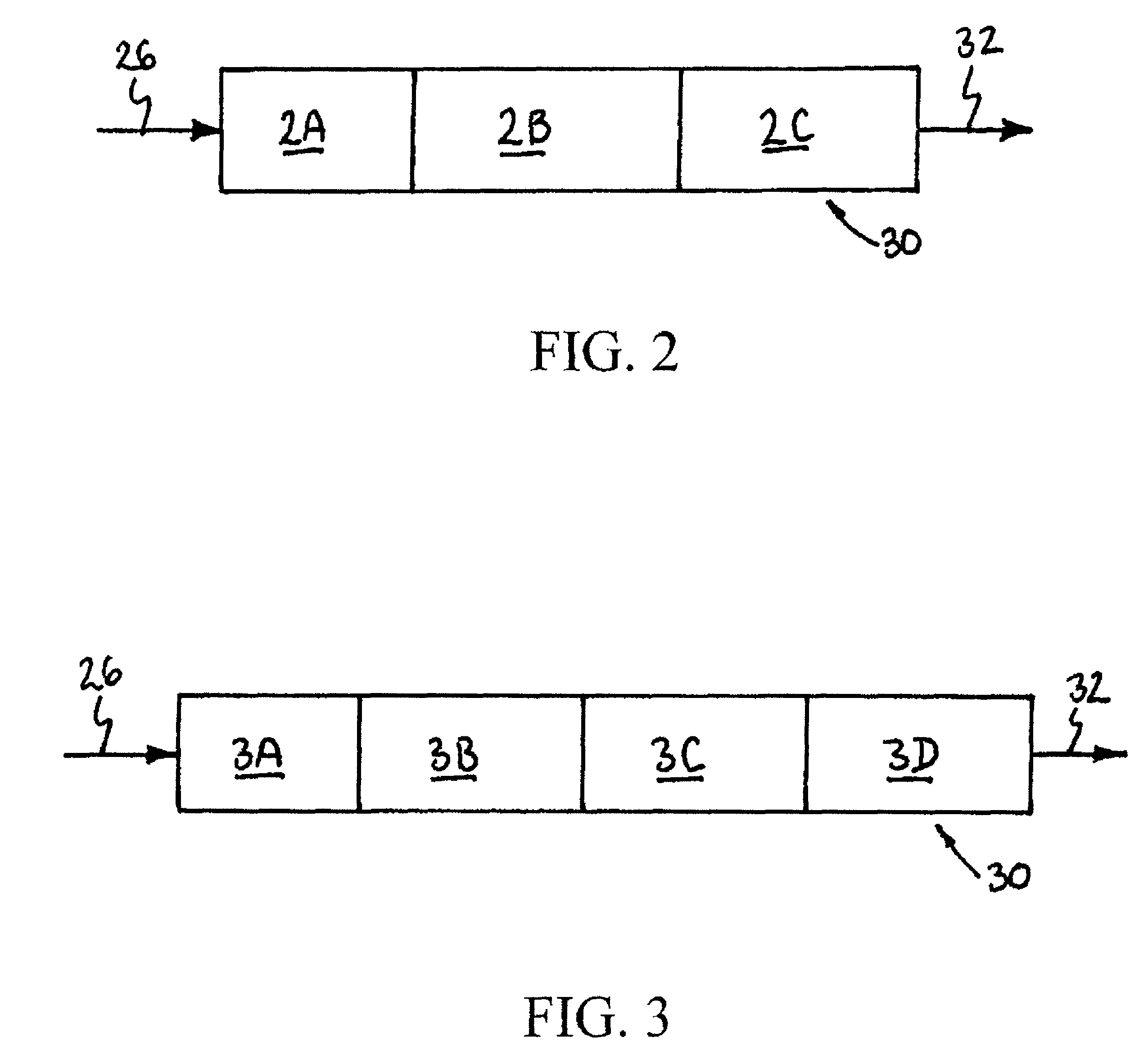
[0202]In addition, a second simulation has been carried out which is the same as the first simulation with the exception that an oxidation catalyst is added to the adsorbent beds of the adsorption system, to convert CO and NO in the presence of O2 into carbon dioxide and NO2 respectively.

[0203]A figure for the temperature of stream 46 leaving the adsorption system 30 af...


PUM

PropertyMeasurementUnit
pressureaaaaaaaaaa
pressureaaaaaaaaaa
pressureaaaaaaaaaa

Abstract

NO2 may be removed from a carbon dioxide feed gas comprising NOx and at least one “non-condensable” gas as contaminants by passing the feed gas at a first elevated pressure through a first adsorption system that selectively adsorbs at least NO2 to produce at least substantially NO2-free carbon dioxide gas. The adsorption system is at least partially regenerated using a carbon dioxide-rich gas recovered from the substantially NO2-free carbon dioxide gas after purification. The invention has particular application in removing NOx and water from flue gas generated by oxyfuel combustion.

Description

BACKGROUND OF THE INVENTION[0001]The present invention relates to a method for removing at least nitrogen dioxide (NO2) from carbon dioxide gas comprising NOx and at least one “non-condensable” gas as contaminants. The method typically also removes from the feed gas one or more of at least NO, N2O, water, SOx and CO if present in the gas as further contaminants. The invention has particular application in the purification of crude carbon dioxide, e.g. flue gas generated by oxyfuel combustion of a fuel such as hydrocarbons, carbonaceous fuels and biomass. The method has particular application in treating flue gas from a power station in which pulverized coal is combusted in a boiler to produce steam for electric power generation.[0002]The term “SOx” means oxides of sulfur and includes sulfur dioxide (SO2) and sulfur trioxide (SO3). The term “NOx” means oxides of nitrogen and includes primarily NO and nitrogen dioxide (NO2). NOx may comprise one or more other oxides of nitrogen includ...

Claims


Application Information

Patent Timeline
Patent Type & Authority Patents(United States)
IPC IPC(8): C01B31/20C01B32/50
CPCB01D53/75F23J15/02F25J3/067B01J20/08B01J20/18B01J20/3408B01J20/3433B01J20/3483B01J20/3491B01J20/103B01J20/28052B01J20/043B01J20/06B01D53/02B01D53/002F25J2220/84B01D53/0462B01D53/229B01D53/8625B01D53/8646B01D2253/102B01D2253/104B01D2253/106B01D2253/108B01D2253/1124B01D2255/20723B01D2255/2073B01D2255/20761B01D2255/20776B01D2256/22B01D2257/302B01D2257/404B01D2257/502B01D2257/80B01D2258/0283B01D2259/40054B01D2259/4145F23J2215/10F23J2215/101F23J2215/20F23J2215/50F23J2219/60F25J2205/40F25J2205/66F25J2205/80F25J2210/70F25J2220/82F25J2230/30F25J2230/32F25J2230/80F25J2240/90Y02C10/12B01J23/22B01J23/30B01J23/34B01J23/72B01J2220/56B01J2220/603Y02A50/20Y02C20/40Y02E20/34Y02E20/32
Inventor WRIGHT, ANDREW DAVIDFOGASH, KEVIN BOYLEWHITE, VINCENTKLOOSTERMAN, JEFFREY WILLIAMGOLDEN, TIMOTHY CHRISTOPHERHIGGINBOTHAM, PAUL
Owner AIR PROD & CHEM INC
Why Eureka
Try Eureka