Pair of optically locked semiconductor narrow linewidth external cavity lasers with frequency offset tuning

a technology of external cavity lasers and optical locking, which is applied in the direction of semiconductor lasers, semiconductor laser arrangements, instruments, etc., can solve the problems of slow frequency tuning speed of lasers, limited tens of millisecond range, and high sensitive to environmental changes, and achieve long-term stable operation

Active Publication Date: 2011-09-20
OPTASENSE
View PDF13 Cites 10 Cited by
  • Summary
  • Abstract
  • Description
  • Claims
  • Application Information

AI Technical Summary

Benefits of technology

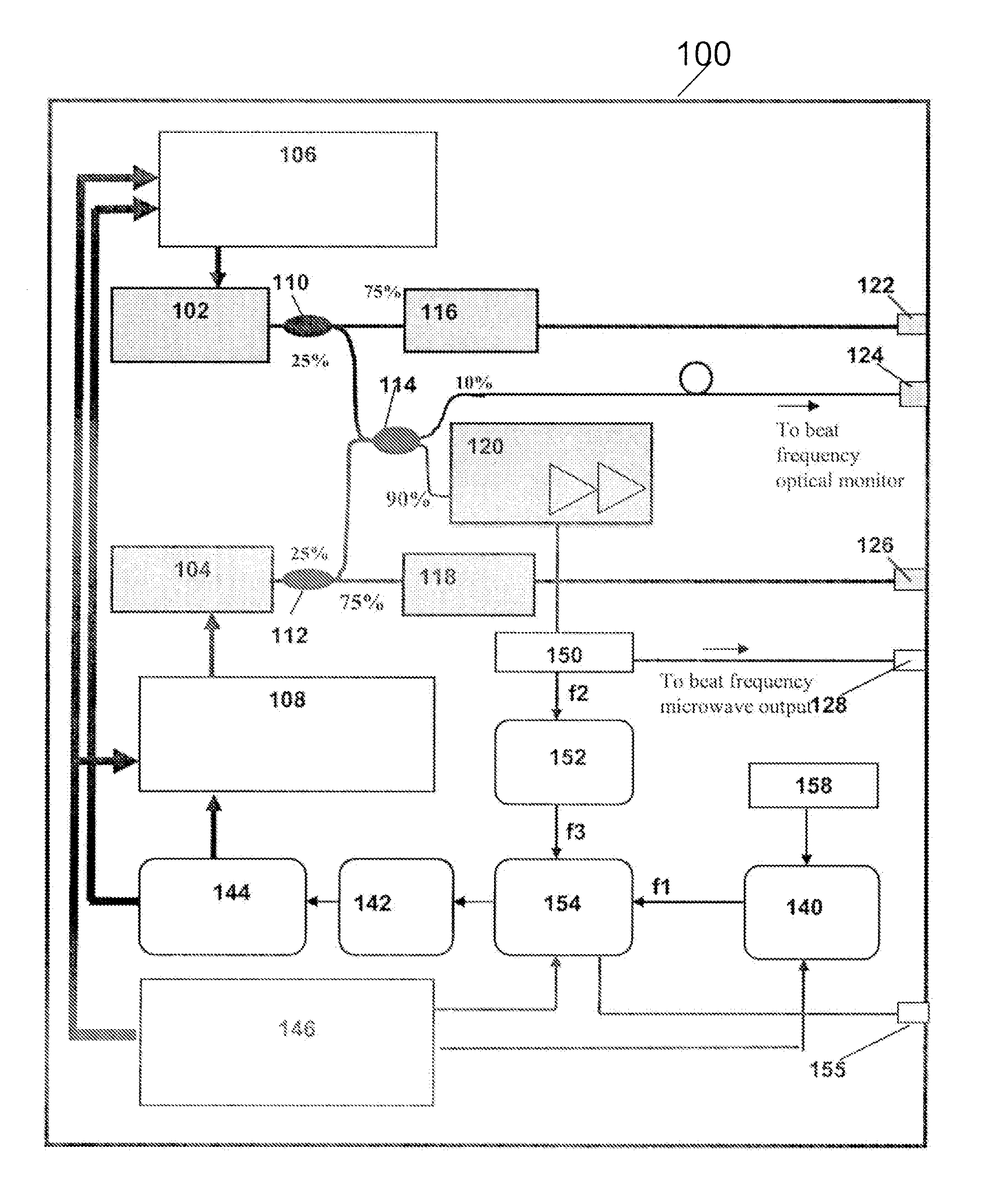
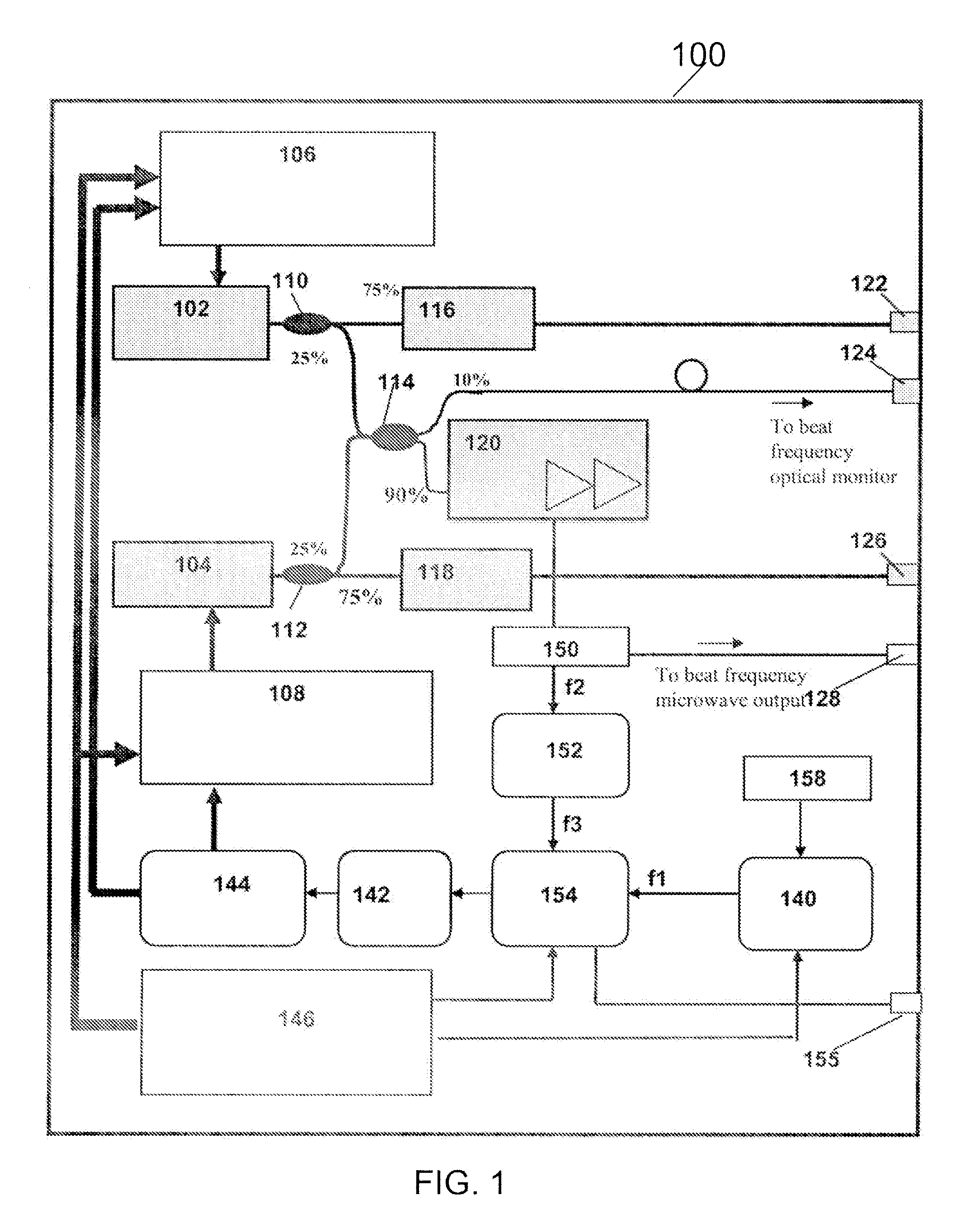
[0008]The present invention describes a high-performance OPLL system having a pair of narrow-linewidth and low-frequency-noise semiconductor-based ECLs, associated polarization-maintaining (PM) optical components, and associated opto-electronic sub-system modified to accommodate the characteristics of the ECLs. The system offers long-term stable operation, and is housed within a small form-factor package.
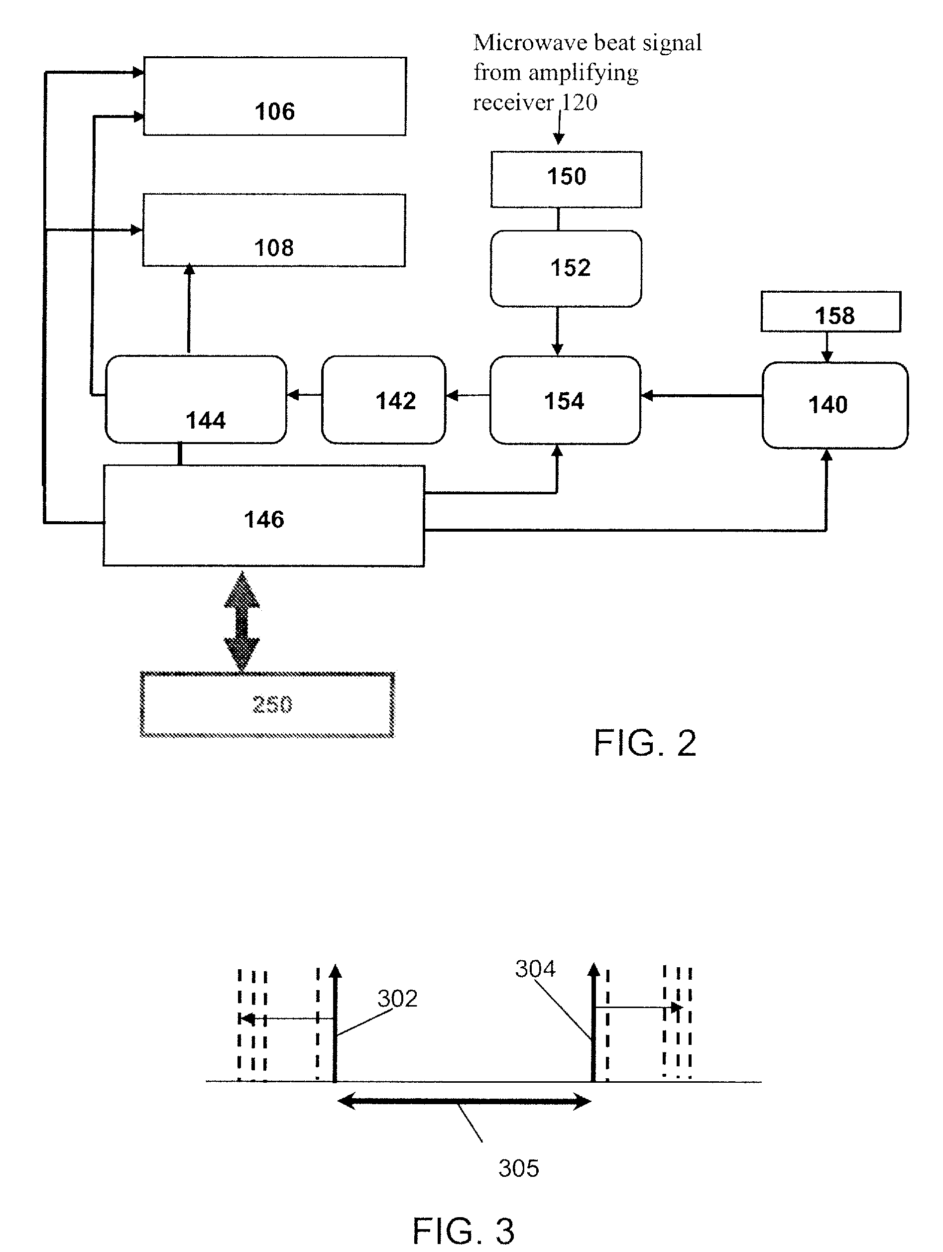
[0009]According to certain aspects of the present invention, an OPLL system is disclosed, comprising: a first (master) ECL and a second (slave) ECL, both having a narrow linewidth and low frequency-noise; a first controller-modulator that controls a master ECL; a second controller-modulator that controls a slave ECL, both controller-modulators being precision modules with low frequency-noise temperature and current control circuitry; a microwave heterodyne receiver that receives coherent heterodyne optical beat signal from the master and the slave ECLs, and outputs an amplified microwave beat frequency signal therefrom; a direct digital synthesizer (DDS) that supplies a control frequency to an electronic phase lock loop (PLL) circuit that receives the beat frequency, and generates a phase error signal; and a loop filter that provides gain in the bandwidth of frequency response of the controller-modulators, and feeds the error signal and a correction signal to the first and the second controller-modulators via a laser select logic (LSL) module, to achieve a stable and identical phase performance of both ECLs.
[0010]According to another aspect of the invention, an OPLL system is disclosed, comprising: a master ECL, having a narrow linewidth and low frequency noise, a first controller-modulator that controls the master ECL, a slave ECL, substantially similar (in all characteristics) to the master ECL, a second controller-modulator that controls the slave ECL, a optical microwave receiver that receives an optical beat frequency via a polarization maintaining (PM) fiber, and outputs an amplified a beat frequency signal therefrom; a DDS module that supplies an intermediate control frequency (IF); a pre-scalar module that scales down the receiver microwave beat frequency; an electronic PLL circuit that receives the scaled down beat frequency and the IF control frequency, and generates a phase error signal therefrom; and a loop filter that provides gain in the BW of frequency response of the controller-modulators, and feeds and distributes the error signal and a correction signal to the first and the second controller-modulators via a LSL module. to achieve a stable and identical phase performance of both the master and slave ECLs.

Problems solved by technology

Such lasers have slow speed of frequency tuning (typically, tens of millisecond range) limited by the speed of piezo-electric transducer (PZT) used to change the cavity length of the lasers.
Another disadvantage of lasers is that they are usually highly sensitive to environmental changes, and require frequent calibration and maintenance to achieve desired performance.
OPLL based on DFB lasers require very large bandwidth (BW) of operation because of the large linewidth of DFB lasers (more than a few hundred kHz).
Presence of the phase reversal frequency within the BW of OPLL leads to instability in operation and requires complicated electronics for correcting such effects.
Another adverse problem with DFB based OPLL is their very high sensitivity of FM response caused by current and temperature response to the environmental changes, which forces the OPLL to “ramp” outside of the voltage locking range, and correspondingly lose their lock.

Method used


Image

  • Pair of optically locked semiconductor narrow linewidth external cavity lasers with frequency offset tuning
  • Pair of optically locked semiconductor narrow linewidth external cavity lasers with frequency offset tuning
  • Pair of optically locked semiconductor narrow linewidth external cavity lasers with frequency offset tuning

Examples


Embodiment Construction

[0021]The present invention will now be described in detail with reference to the drawings, which are provided as illustrative examples of the invention so as to enable those skilled in the art to practice the invention. Notably, the figures and examples below are not meant to limit the scope of the present invention to a single embodiment, but other embodiments are possible by way of interchange of some or all of the described or illustrated elements. Moreover, where certain elements of the present invention can be partially or fully implemented using known components, only those portions of such known components that are necessary for an understanding of the present invention will be described, and detailed descriptions of other portions of such known components will be omitted so as not to obscure the invention. Embodiments described as being implemented in software should not be limited thereto, but can include embodiments implemented in hardware, or combinations of software and...


PUM


Abstract

An optical phase lock loop (OPLL) system is disclosed that includes a master external cavity laser (ECL), and a substantially identical slave ECL. The master and slave ECLs are fabricated using a planar semiconductor device with waveguide-integrated planar Bragg gratings (PBG). Both the master and slave ECLs have a narrow linewidth and a low frequency-noise. Each of the ECLs has their own controller-modulator circuits for thermal tuning or electrical tuning via direct modulation. A laser-select-logic (LSL) module receives and processes a filtered phase error signal from a loop filter coupled to an electronic PLL device, and directs the processed phase error signal to one or both of the master and slave controller-modulators according to a logical determination of a required mode of operation of the OPLL system in order to achieve a stable and identical phase performance of the master and the slave ECLs. The required mode of operation is chosen from a locking mode, a prediction mode, a tracking mode, and a searching mode.

Description

CROSS REFERENCE TO RELATED APPLICATION[0001]This application claims priority from U.S. Provisional Application Ser. No. 61 / 181,192 filed May 26, 2009.FIELD OF THE INVENTION[0002]The present invention relates to implementing a high-performance, high-stability, small footprint Optical Phase Locked Loop system using a pair of semiconductor external cavity lasers.BACKGROUND[0003]Phase Lock Loop (PLL) is a common electronic feedback system used in various electronic systems (e.g., radars, communications, TV, computers, cell phones, etc.) Some of the key parts of a PLL system include a phase detector (PD), a local oscillator (LO), a loop filter, etc. The LO frequency can be tuned by changing the input voltage or current. In a PLL circuit, the LO is forced to follow frequency / phase of an incoming / reference signal. The LO is locked onto the incoming signal such that LO and incoming / reference signal have ‘identical’ frequency / phase performance in the bandwidth of interest.[0004]Optical Phase...

Claims


Application Information

Patent Timeline
Patent Type & Authority Patents(United States)
IPC IPC(8): H01S3/13
CPCH01S5/14H01S5/40H01S5/0623
Inventor KUPERSHMIDT, VLADIMIR
Owner OPTASENSE
Why Eureka
Try Eureka