
System and method for the production of hydrogen

a technology of hydrogen and production method, applied in the field of system and a method for the production of hydrogen, can solve the problems of inequitable geographical distribution of global petroleum resources, affecting global climate disruption, and correlated consumption of fossil fuel with economic and population growth

Active Publication Date: 2011-10-11
GENERAL ELECTRIC CO
View PDF14 Cites 7 Cited by
  • Summary
  • Abstract
  • Description
  • Claims
  • Application Information

AI Technical Summary

Benefits of technology

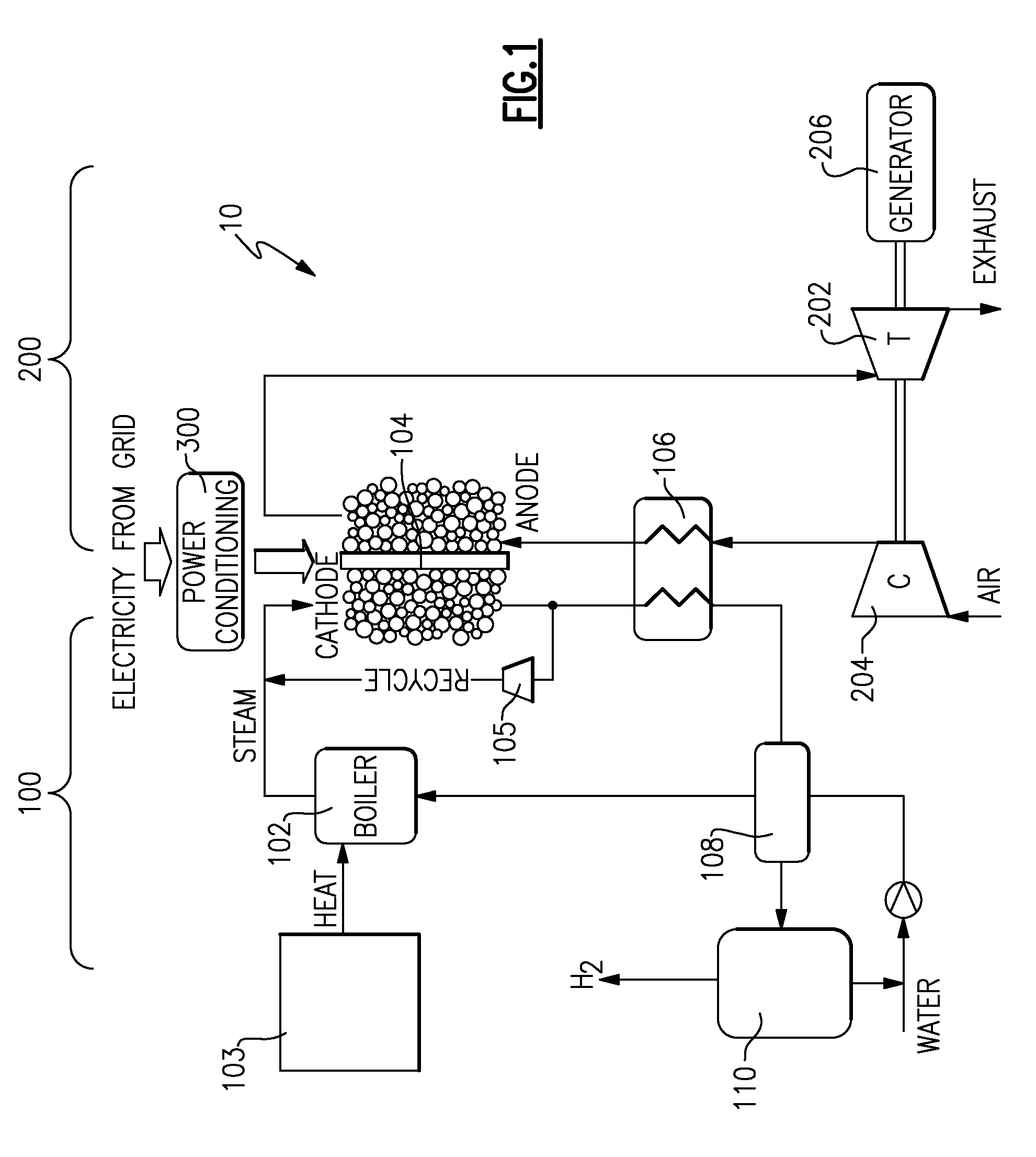
Disclosed herein is a hydrogen producing system comprising a solid oxide electrolyzer cell having a cathode side and an anode side; wherein the cathode side comprises a heat exchanger that lies down stream of an outlet of the solid oxide electrolyzer cell; a high temperature heat source that generates steam in a boiler at a temperature of about 400 to about 700° C. and a pressure of about 3 to about 20 kg / cm2; and wherein the boiler is located upstream of the solid oxide electrolyzer cell; and further wherein the boiler is in fluid communication with an inlet located at the cathode side of the solid oxide electrolyzer cell, wherein the heat exchanger lies upstream of an inlet on the cathode side of the solid oxide electrolyzer cell; and wherein the heat exchanger is operative to extract heat from the steam and hydrogen emanating from the cathode side of the solid oxide electrolyzer cell.
Disclosed herein too is a method comprising generating steam at a temperature of about 400 to about 700° C. and a pressure of about 3 to about 20 kg / cm2 using a high temperature heat source; electrolyzing the steam to form hydrogen and oxygen in a solid oxide electrolyzer cell; and extracting heat from the hydrogen and steam to heat steam in a heat exchanger.

Problems solved by technology

Fossil fuel combustion has been identified as a significant contributor to numerous adverse environmental effects.
In particular, increased concentrations of GHG's are a significant concern since the increased concentrations may cause a change in global temperature, thereby potentially contributing to global climatic disruption.
One problem associated with the use of fossil fuel is that the consumption of fossil fuel correlates closely with economic and population growth.
A further problem associated with the use of fossil fuels is related to the inequitable geographical distribution of global petroleum resources.
In particular, many industrialized economies are deficient in domestic supplies of petroleum, which forces these economies to import steadily increasing quantities of crude oil in order to meet the domestic demand for petroleum derived fuels.
But these approaches cannot currently compete, on an economic basis, with hydrogen produced by steam methane reforming (SMR) of natural gas.
This type of system risks steam ingress into the nuclear core due to the high-pressure steam generators, where the steam can be at a higher pressure than the primary helium coolant.
Steam ingress into the core is undesirable because it can corrode the graphite moderator and graphite-coated fuel, and can also cause a reactivity insertion due to the moderating effect of steam.
A further shortcoming of these systems is that the electrical generation and hydrogen generation are coupled together in the same system and are in fluid communication with each other, making the system inflexible and potentially not optimized.
Additionally, these systems may be limited to low current densities and therefore low hydrogen production per unit area of cell because these systems do not have a sweep gas to remove waste heat from the anode.
These systems thus require an additional heat exchanger that interfaces with the nuclear reactor, which incurs additional cost and introduces a risk of air ingress into the nuclear reactor.
These systems may suffer corrosion or loss of performance of the anode due to the presence of steam at the anode.

Method used


Image

  • System and method for the production of hydrogen
  • System and method for the production of hydrogen
  • System and method for the production of hydrogen

Examples


example

This numerical example has been performed to demonstrate one exemplary method of functioning of the hydrogen producing system. This example has been conducted to demonstrate the advantages that are available by generating hydrogen according to the disclosed method.

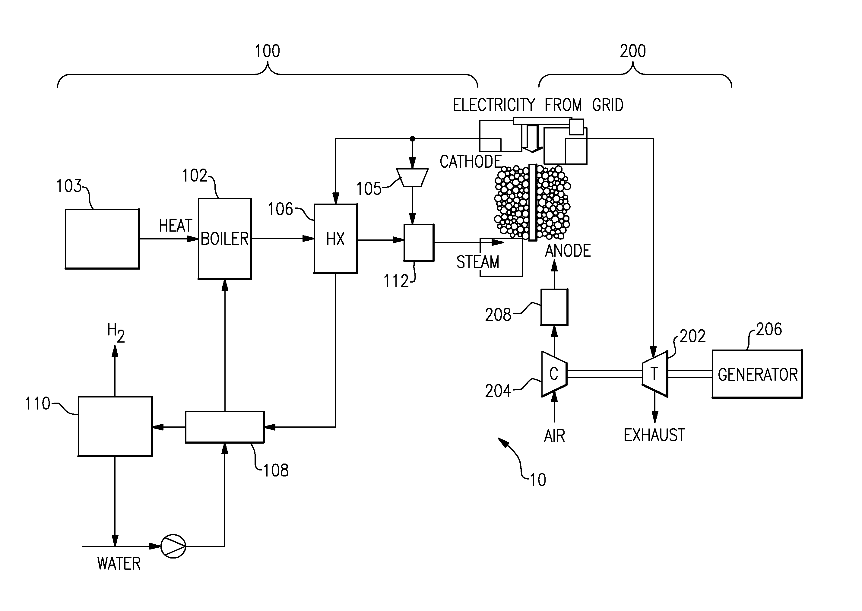
FIG. 3 is a depiction of the system upon which the numerical example was performed. FIG. 3 comprises the same elements depicted in the FIG. 1. Each element in the FIG. 3 however, has its inlet and outlet points numbered. Table 1 shows the respective values (at each of the inlet and outlet points) for the water / steam pressure and temperature for an optimized system that generates electricity and steam.

TABLE 1Point #Pressure (kg / cm2)Temperature (° C.)18.1875028.1675937.7179247.7179257.4871067.4871077.1837681.022098.7920.5108.59167118.33290128.08748137.88792147.88792151.02410161.0220176.8225

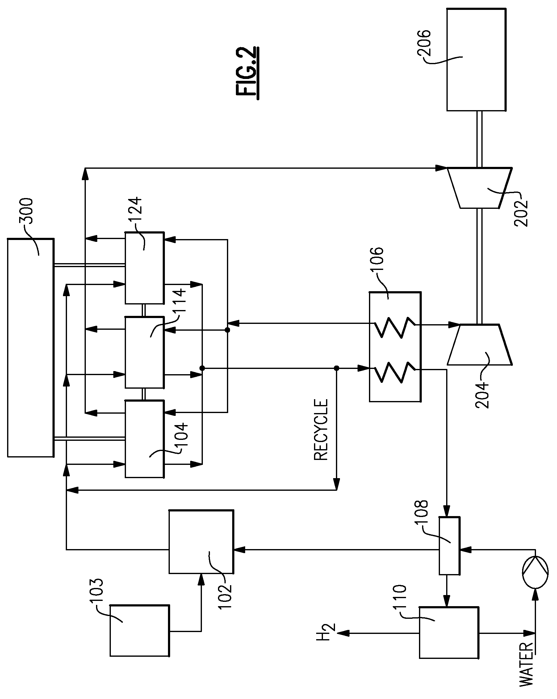
Referring now to FIG. 4, another embodiment of the hydrogen producing system 10 is shown and described. In the earlier embodiments shown ...


PUM

PropertyMeasurementUnit
temperatureaaaaaaaaaa

Abstract

Disclosed herein are a system and a method for the production of hydrogen. The system advantageously combines an independent high temperature heat source with a solid oxide electrolyzer cell and a heat exchanger located between the cathode inlet and the cathode outlet. The heat exchanger is used to extract heat from the molecular components such as hydrogen derived from the electrolysis. A portion of the hydrogen generated in the solid oxide electrolyzer cell is recombined with steam and recycled to the solid oxide electrolyzer cell. The oxygen generated on the anode side is swept with compressed air and used to drive a gas turbine that is in operative communication with a generator. Electricity generated by the generator is used to drive the electrolysis in the solid oxide electrolyzer cell.

Description

BACKGROUNDThis disclosure relates to a system and a method for the production of hydrogen. In particular, this disclosure relates to a system and a method for the production of hydrogen using a solid oxide electrolyzer in conjunction with a high temperature heat source.Fossil fuel combustion has been identified as a significant contributor to numerous adverse environmental effects. For example, poor local air quality, regional acidification of rainfall that extends into lakes and rivers, and a global increase in atmospheric concentrations of greenhouse gases (GHG), have all been associated with the combustion of fossil fuels. In particular, increased concentrations of GHG's are a significant concern since the increased concentrations may cause a change in global temperature, thereby potentially contributing to global climatic disruption. Further, GHG's may remain in the earth's atmosphere for up to several hundred years.One problem associated with the use of fossil fuel is that the ...

Claims


Application Information

Patent Timeline
Patent Type & Authority Patents(United States)
IPC IPC(8): C25B9/06C25B1/04C25B1/10C25B1/02C25B9/17
CPCC25B1/02C25B15/08F22B31/00
Inventor PETER, ANDREW MAXWELLRENOU, STEPHANERUUD, JAMES ANTHONYCRIDER, LEAH DIANEBROWALL, KENNETH WALTERBALAN, CHELLAPPA
Owner GENERAL ELECTRIC CO
Learn More