
Electric lamp with light-absorbing coating, precursor suspension for such a coating and method of making such a lamp

a technology of light-absorbing coating and electric lamps, which is applied in the field of electric lamps, can solve the problems of parasitic light in the light beam, the light-absorbing coating is too easily removed from the lamp vessel, and the stray light/glare in automotive applications, etc., and achieves better light absorption and impermeability, less scratching or flaking, and better adhesion.

Inactive Publication Date: 2011-10-18
LUMILEDS
View PDF9 Cites 0 Cited by
  • Summary
  • Abstract
  • Description
  • Claims
  • Application Information

AI Technical Summary

Benefits of technology

The invention is about an electric lamp with a light-absorbing coating that has high light absorption and is durable and harmless to the environment. The coating is made of a mixture of iron and silicon powders, which are suspended in a binder made of ethyl silicate hybrid. The ratio of iron to silicon is important - too low and the coating may not have the desired properties, while too high can result in the coating being easily removable. The coating is applied to the lamp by heat treatment for a few seconds at a temperature of 700-900°C. The coating has good light-absorbing properties and reflects little light. It can be controlled by adjusting the viscosity of the suspension and has a thickness of 0.007-0.15 mm. The use of ethyl silicate hybrid binders provides improved storage stability and processing properties compared to conventional ethyl silicate. The ratio of iron compounds to silicon compounds is important - within certain ranges, the coatings have good properties.

Problems solved by technology

A silicon / silicon dioxide ratio of less than 0.5 causes the light-absorbing properties of the light-absorbing coating to be too low, which might result in disturbing stray light / glare in automotive applications.
A silicon / silicon dioxide ratio of more than 12 causes the light-absorbing coating to be too easily removable from the lamp vessel, i.e. in that it can be scratched off comparatively easily or even rubbed off.
Said reflected light may result in parasitic light in a light beam formed by an optical system, for example, a reflector and a lens.

Method used


Image

  • Electric lamp with light-absorbing coating, precursor suspension for such a coating and method of making such a lamp
  • Electric lamp with light-absorbing coating, precursor suspension for such a coating and method of making such a lamp
  • Electric lamp with light-absorbing coating, precursor suspension for such a coating and method of making such a lamp

Examples


Embodiment Construction

shown in the drawing, in which

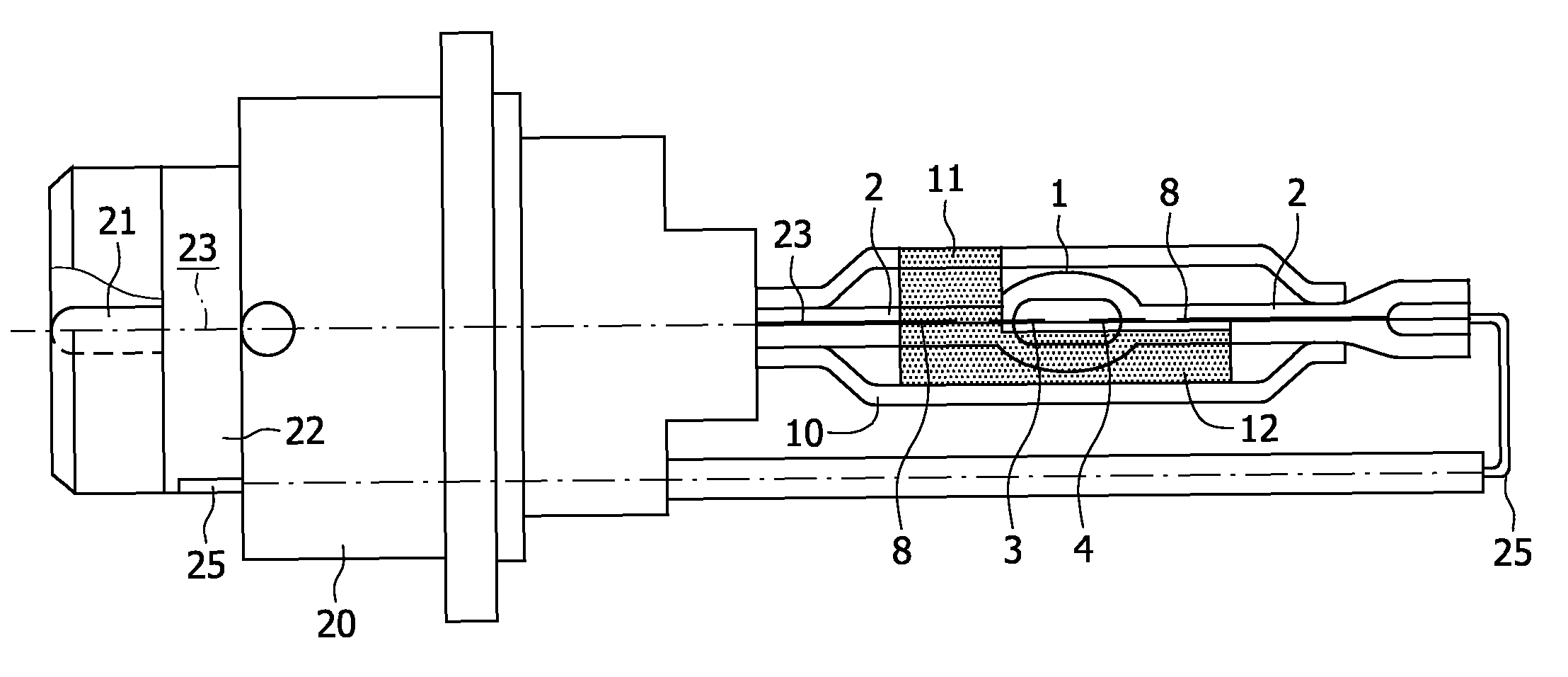
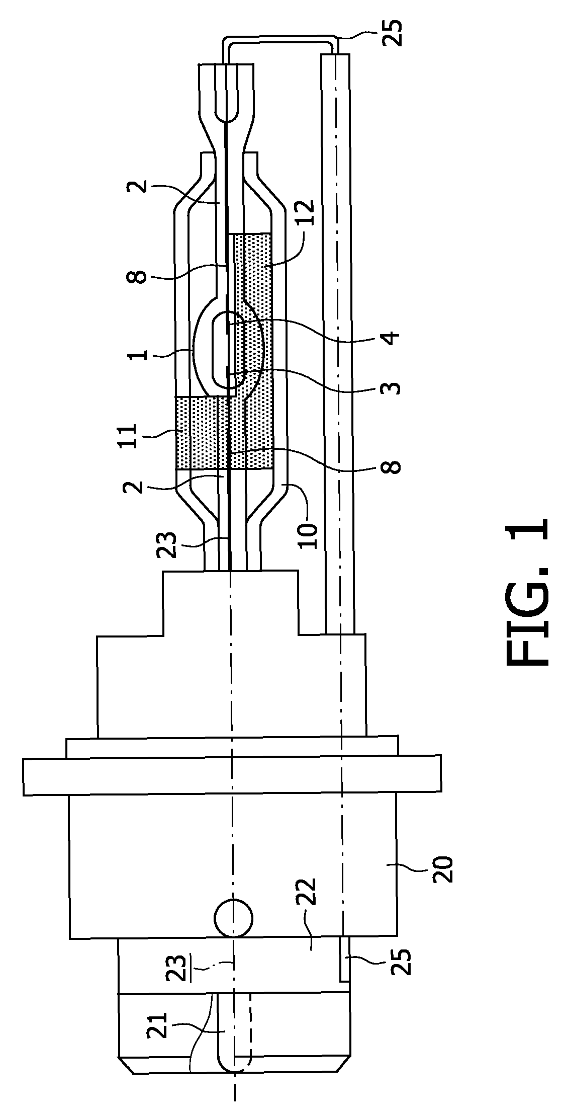
[0010]FIG. 1 shows a discharge lamp in a side elevation, partly in a cross-section; and

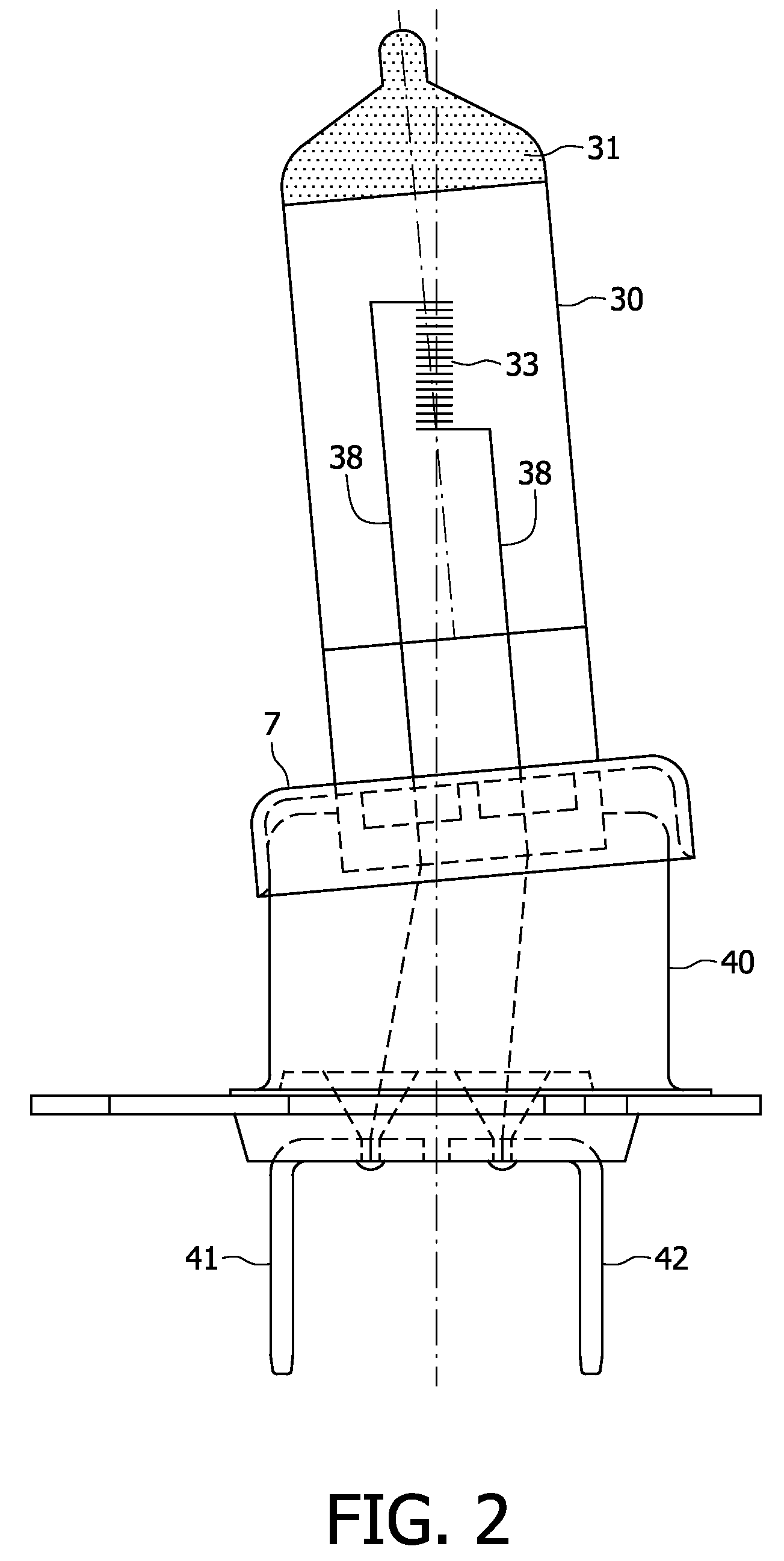
[0011]FIG. 2 shows an incandescent lamp in a side elevation.

DESCRIPTION OF EMBODIMENTS

[0012]In FIG. 1, the high-pressure discharge lamp has a quartz glass lamp vessel 10 which is sealed in a gastight manner by seals 2, the lamp vessel accommodating an electric element. The electric element comprises electrodes 3, 4 in an inner quartz glass envelope 1 containing an ionizable filling. The filling comprises, for example, mercury, a mixture of metal halide such as sodium iodide and scandium iodide, and a rare gas such as, for example, xenon, for example, with a filling pressure of several bars. Current conductors 8, 23; 8, 25 comprising Mo-foils embedded in the seals 2 of the lamp vessel are connected to the electrodes and issue from the lamp vessel to the exterior. The lamp has a lamp cap 20 fitted with contacts 21, 22.

[0013]The lamp vessel is locally covered with a ligh...


PUM

PropertyMeasurementUnit
thicknessaaaaaaaaaa
temperatureaaaaaaaaaa

Abstract

An electric lamp is described, which has a quartz glass lamp vessel (10) accommodating an electric element (3, 4). The lamp vessel locally has a light-absorbing, non-reflective coating (11, 12). The coating mainly consists of iron, iron oxide, silicon, and silicon dioxide, the ratio of the weight percentages of iron (compounds) and silicon (compounds) being in the range of 0.17<=iron (compounds) / silicon (compounds)<-12, and the ratio of the weight percentages of silicon and silicon dioxide being in the range of 0.5<=silicon / silicon dioxide<=50.

Description

FIELD OF THE INVENTION[0001]The invention relates to an electric lamp as defined in the pre-characterizing part of claim 1. The invention further relates to a suspension to be used for said electric lamp and a method of manufacturing such a lamp.BACKGROUND OF THE INVENTION[0002]An electric halogen incandescent lamp of this type is known from DE 3827451. Besides iron oxide, the known light-absorbing coating further comprises titanium oxide, manganese oxide and magnetite, FeO4, as pigments and, before being burned onto the glass of the lamp vessel, ethyl silicate as an adhesive. The known coating is obtained from a suspension which additionally comprises sodium metaphosphate, glycol, monobutyl glycol ether, and ethanol. The suspension has a relatively complicated composition. The known suspension has the disadvantage of a relatively short shelf life of about 3 days, and when burned onto the lamp vessel and being converted into the light-absorbing coating, this light-absorbing coating ...

Claims


Application Information

Patent Timeline
Patent Type & Authority Patents(United States)
IPC IPC(8): H01J17/16H01J61/30
CPCC03C17/004C03C17/009H01K1/32C09D5/00H01J61/35C03C2217/213C03C2217/217
Inventor SCHLOEMER, HEINZ JOSEF
Owner LUMILEDS
Learn More