Hydrotreatment process

a hydrotreatment process and fuel technology, applied in the direction of hydrocarbon oil treatment products, biofeedstock, chemistry apparatus and processes, etc., to achieve the effect of simple and not least safer production of additional hydrogen

Inactive Publication Date: 2011-10-25
HALDOR TOPSOE AS
View PDF9 Cites 9 Cited by
  • Summary
  • Abstract
  • Description
  • Claims
  • Application Information

AI Technical Summary

Benefits of technology

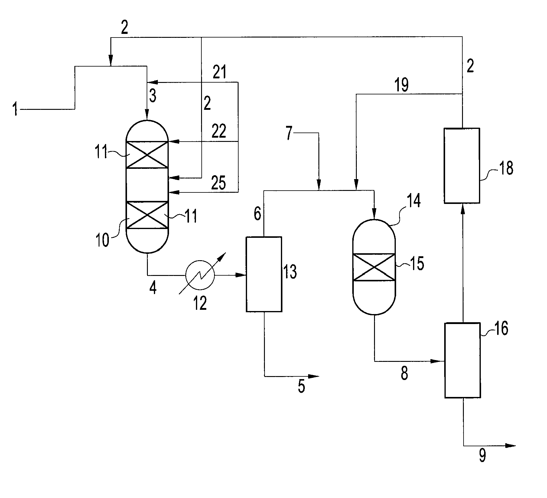
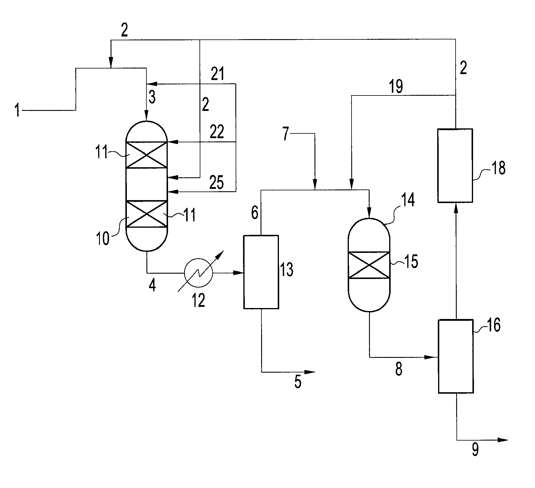
[0007]We have now found that by hydrotreating a hydrocarbon fuel of which a portion consists of renewable organic material it is possible to in-situ produce carbon monoxide in the gas, i.e. during operation of the process, thereby enabling a simpler and not least safer production of additional hydrogen compared to prior art processes. A highly attractive alternative fuel in the form of a renewable organic material may thus be used without resorting to highly hazardous solutions such as injection of oxygen from an external source, which additionally requires dedicated and highly expensive separate plants for its preparation, or separate and highly expensive plants for the provision of additional hydrogen such as reforming plants for the production of synthesis gas containing carbon monoxide and hydrogen.
[0013]By treating a hydrocarbon fuel containing renewable organic material according to the process of the invention it is possible to convert in-situ produced carbon monoxide and water to CO2 and H2, thereby enabling removal of the generated CO and H2O that otherwise can inhibit catalyst activity in the hydrotreating unit and limit its capacity also because of operational restraints on allowed concentrations of impurities in the recycle gas stream. A highly attractive alternative fuel in the form of a diesel fully or partly based on renewable sources may thus be produced without being forced to limit the throughput or resorting to very high purge rates that are otherwise necessary to limit the content of contaminants such as carbon monoxide and which furthermore has a very low affinity for removal in the hydrogen sulphide recovery unit, such as an amine wash unit.
[0019]By the invention it is possible to operate the hydrotreater with a high content of renewable organic material and at the same time it is possible to obtain an elevated content of hydrogen in the hydrogen-rich recycle stream, thereby also reducing the need of addition of highly expensive hydrogen through external sources.
[0028]We have also found that conventional hydrotreating catalysts are able to establish near thermodynamic equilibrium for the water-gas-shift reaction in the hydrotreating stage and yet by the addition of water to the hydrotreating stage the equilibrium of the water-gas shift reaction is shifted even more towards carbon dioxide and hydrogen without affecting the hydrodesulfurisation or hydrodenitrification capacity of the catalyst.
[0031]Without water addition the in-situ formed carbon monoxide is at least partly converted to methane under consumption of valuable hydrogen. By adding water to the hydrotreating stage methane formation is depressed and the thus associated consumption of valuable hydrogen is reduced. In addition, it is possible to obtain a lower CO / CO2 ratio and as a result there is less risk of catalyst poisoning by the presence of carbon monoxide in the hydrotreater. Water may also be added directly to the one or more fixed beds of hydrotreating catalyst.
[0032]Moreover, by the simple addition of water the amount of renewable organic material, preferably biodiesel in the hydrocarbon fuel passed to the hydrotreating stage can be increased significantly, for instance from about 5 vol % renewable organic material to 10 vol % or 20 vol % or even more, for instance 30 vol % or even 100 vol % biodiesel. Only up to levels of about 5 vol % renewable organic material in the feedstock it is possible to operate the hydrotreating process without shift and / or water addition. The other component in the hydrocarbon fuel may be a conventional oil fraction such as light gas oil, light cycle oil, coker gas oil or vacuum gas oil (VGO).

Problems solved by technology

Hydrocarbon feedstocks and in particular heavy hydrocarbons such as oil and diesel usually contain organic sulphur and nitrogen compounds that in subsequent stages represent undesired impurities because of their negative effect on catalyst activity.

Method used


Image

  • Hydrotreatment process
  • Hydrotreatment process

Examples


example 1

[0036]Feedstock A (Table 1) is a mixture of 20% by volume of rapeseed oil and 80% by volume vacuum gas oil. The pure vacuum gas oil is denoted Feedstock B. Feedstock A was hydrotreated in a once-through pilot plant using 105 ml of a hydrotreating catalyst (Ni and Mo impregnated on an alumina support). The flow of feedstock A was 105 ml / hr corresponding to a LHSV of 1 hr−1. 100% hydrogen (no recycle) at a pressure of 80 bar was co-fed with the liquid stream at a rate of 73.5 Nl / hr corresponding to a H2 / oil ratio of 700 Nl / l. The temperature of the reactor was maintained at 350° C. Product samples were taken of the liquid effluent. The exiting gas from the reactor was analyzed by gas chromatography.

[0037]

TABLE 1Properties of feedstock A and B used in the following examplesPropertyFeedstock AFeedstock BS.G.0.91390.9123S (wt %)2.232.88N (wt ppm)494737H (wt %)12.012.2Simulated Distillation (° C.) 5 wt %362.4363.610 wt %376.6376.430 wt %404.0401.250 wt %422.2416.470 wt %442.0430.890 wt %6...

example 2

[0043]Feedstock A from Example 1 is processed using the same catalyst and conditions (temperature=350° C., pressure=80 barg, LHSV=1 hr−1, H2 / oil=700 Nl / l) as in Example 1, however H2O was added to the feed before it entered the reactor. Two experiments with 2.1 g H2O / hr and 4.2 g H2O / hr, respectively, were conducted. These water flows correspond to 2.0 vol % and 4.0 vol % of the mass-flow of feedstock A. The results are shown in Table 3, yields are calculated based on the flow of fresh feedstock (excluding H2O).

[0044]

TABLE 3Properties of products in Example 2Product fromProduct fromFeedstock A.Feedstock A.2.1 g H2O / hr4.2 g H2O / hradded upstreamadded upstreamPropertyreactorreactorLiquid Product AnalysesH (wt %)13.413.4S.G.0.8610.862Yields (wt % Fresh HC Feed)CO0.310.25CO20.630.82H2O3.795.82CH40.140.13C2H60.050.05C3H80.890.85i-C4 + n-C40.050.05H2S + NH32.362.36Liquid Product95.3095.34H2 Consumption (Nl / l)141140Exit Gas Composition (vol %)CO0.370.29CO20.480.60H2O7.0510.39CH40.290.26H288...


PUM

PropertyMeasurementUnit
wt %aaaaaaaaaa
pressuresaaaaaaaaaa
pressuresaaaaaaaaaa

Abstract

A process for the hydrotreating of fuels with co-production of hydrogen during operation of the process, which enables i.e. reduced need of make-up hydrogen in the hydrotreating stage. The hydrocarbon fuel introduced to the hydrotreatment stage is a fuel containing renewable organic material which generates carbon monoxide during operation of the process. The carbon monoxide is then converted to hydrogen in the recycle loop by a water gas shift stage.

Description

BACKGROUND OF THE INVENTION[0001]The present invention relates to a process for the hydrotreating of fuels with co-production of hydrogen during operation of the process. More particularly the invention relates to a hydrotreating process in which the hydrocarbon fuel contains renewable organic material which generates carbon monoxide during operation of the process. The carbon monoxide is then converted to hydrogen in the recycle loop by a water gas shift stage.[0002]During the refining of oil feeds, hydrotreatment stages are utilized for the removal of impurities such as sulphur and nitrogen. Hydrocarbon feedstocks and in particular heavy hydrocarbons such as oil and diesel usually contain organic sulphur and nitrogen compounds that in subsequent stages represent undesired impurities because of their negative effect on catalyst activity. Additionally, environmental regulations impose a demand on the production of extremely clean transportation fuels with very low sulphur levels, fo...

Claims


Application Information

Patent Timeline
Patent Type & Authority Patents(United States)
IPC IPC(8): C01B3/24C01B3/26
CPCC01B3/16C10G45/28C10G49/007C10G49/20C10G3/46C10G3/52C10G3/54C10G3/42Y02P30/20C10G2300/1011C10G2300/1014C10G2300/4081C10G2400/04C10G2300/207C10G2300/44C10G2300/807C10G45/04C10G67/14
Inventor KNUDSEN, KIM GRONANDERSEN, KIM HEDEGAARDBREIVIK, RASMUSEGEBERG, RASMUS GOTTSCHALCKNIELSEN, POUL ERIK HOJLUND
Owner HALDOR TOPSOE AS
Why Eureka
Try Eureka