System for tactical balloon launch and payload return

a technology for tactical balloons and return systems, applied in the direction of automatic actuation, launch/towing gear, transportation and packaging, etc., can solve the problems of uncontrollable older parachute systems, substantial safety hazards, and large surface area

Active Publication Date: 2011-11-22
LACHENMEIER TIMOTHY T
View PDF10 Cites 57 Cited by
  • Summary
  • Abstract
  • Description
  • Claims
  • Application Information

AI Technical Summary

Benefits of technology

[0006]A cylindrical plastic-film balloon envelope design is used to provide an inexpensive buoyant platform. This design is well-known to those skilled in the art as being easy to manufacture in quantity, because it does not require the design specific curved scams of a so-called “natural shape” envelope. A range of envelope sizes can be provided so that a deployable system can fly individual platforms at any altitude as required by the application and weather conditions; for example, five “family” sizes can cover the range from 60,000 feet to 100,000 feet altitude for one specific payload mass range. A novel adjustable end-fitting can be provided so the specific balloon volume for the desired altitude required can be set at launch time. The system operator simply selects the smallest family size that can reach the required altitude, adjusts the end fitting to the precise balloon length needed, and cuts off excess material. While cylindrical envelopes are used in an embodiment to provide inexpensive lift, other shapes can be used in an alternate embodiment to optimize the flight differently. For example, a natural shape envelope could be used to increase envelope performance or efficiency. Additionally, an aerodynamically shaped envelope could be used to provide a tactically launched high altitude airship. In this case the PRV would be powered to provide the airships propulsion system.
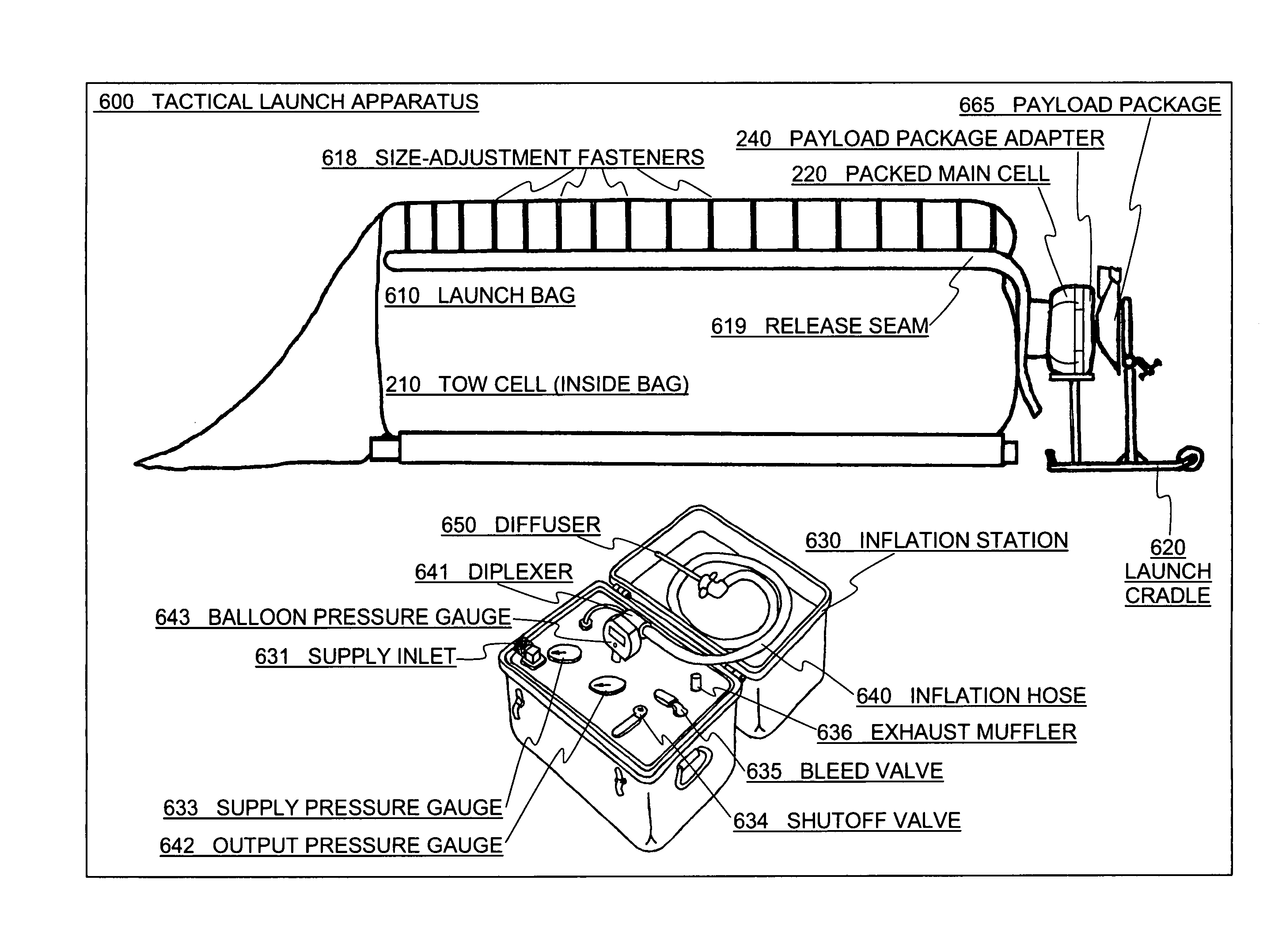
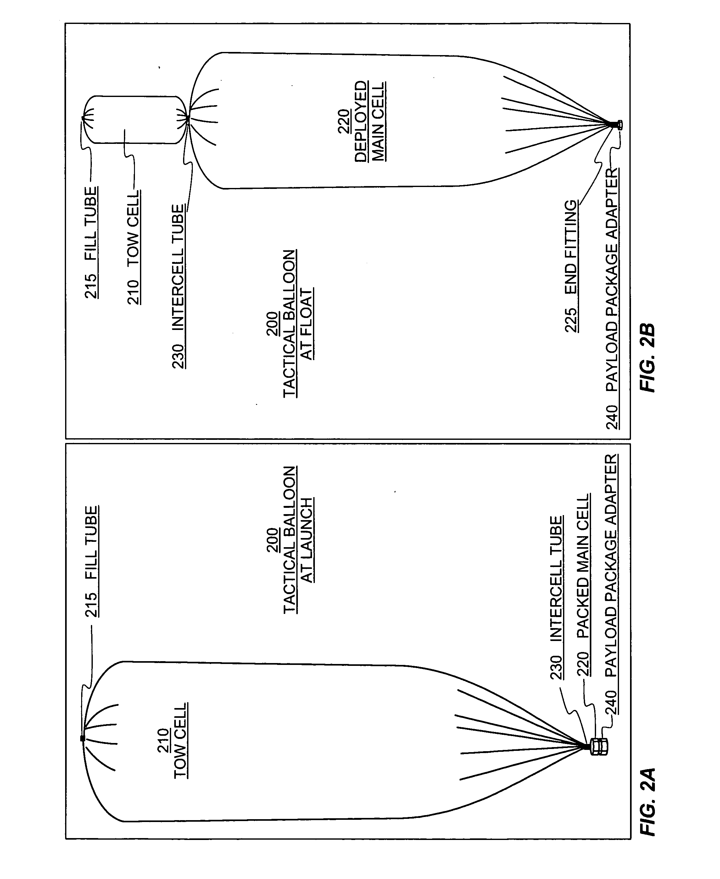
[0007]A pair of techniques from prior art are used to simplify launch procedures and reduce personnel requirements. Because these balloons are very large, when filled they present significant surface area to any wind present at launch. This can be a substantial safety hazard to launch personnel, and creates a great risk of equipment loss. To reduce the surface area at launch, thereby reducing the risks and allowing the platform to be launched in higher winds, a two-cell design is used. A smaller tow cell is attached to the larger main cell, so that the main cell remains unfilled until the pair has accelerated to a speed close to that of the prevailing winds, thereby minimizing the effective wind load on the large main envelope. In addition, the main balloon cell is packed in a deployment bag which includes an automatic release mechanism. When an appropriate altitude or time after launch is achieved, a control system activates the release mechanism, thereby deploying the main cell. Rather than a large sail area at launch, the packed main cell is a compact bundle that does not catch any wind. This elimination of surface area reduces the potential for damage to the gossamer structure due to high wind loading; it also reduces the number of personnel required by making the “launch train” dramatically shorter, in turn eliminating related hazards to personnel and equipment at launch. The tow cell and the main cell are connected via an intercell tube fitting, so that as the combination rises the buoyant gas expands to fill both envelopes.
[0008]For certain flight requirements, management of lifting-gas flow between the tow cell and the main cell may be accomplished via a valve in the intercell tube fitting. This valve is controlled by the platform management computer (see below) via a wireless local communication link that is separate from the main platform communication links described below. Using a wireless link for this local communication avoids the complication of adding flexible wires to the packed main cell, and is a novel approach. During ascent, closing this valve prevents further expansion of the lifting gas into the main cell envelope, which stops the ascent at a particular altitude. Reopening the valve permits the lifting gas to continue expanding into the main cell, thereby resuming the ascent. In an alternate embodiment, the valve may be installed in the tow cell's top fitting, allowing the ascent to be slowed or stopped by venting lifting gas rather than forcing it into the main cell. Depending on altitude, duration, and the amount of free lift required for a particular flight profile, to store the extra lifting gas that may be used in either of these altitude control schemes the tow cell may be enhanced to “super-pressure” capability so that it can accommodate the gas pressure that builds behind the closed valve as the platform rises. While super-pressure balloons themselves are known to those skilled in the art, their simultaneous application as a tow cell and as a gas reservoir in a multicell platform is novel.

Problems solved by technology

Older parachute systems were uncontrolled, but sometimes provided tracking signals; payload recovery involved either elaborate airborne snatches or extensive hunting over the landing zone.
Because these balloons are very large, when filled they present significant surface area to any wind present at launch.
This can be a substantial safety hazard to launch personnel, and creates a great risk of equipment loss.

Method used


Image

  • System for tactical balloon launch and payload return
  • System for tactical balloon launch and payload return
  • System for tactical balloon launch and payload return

Examples


Embodiment Construction

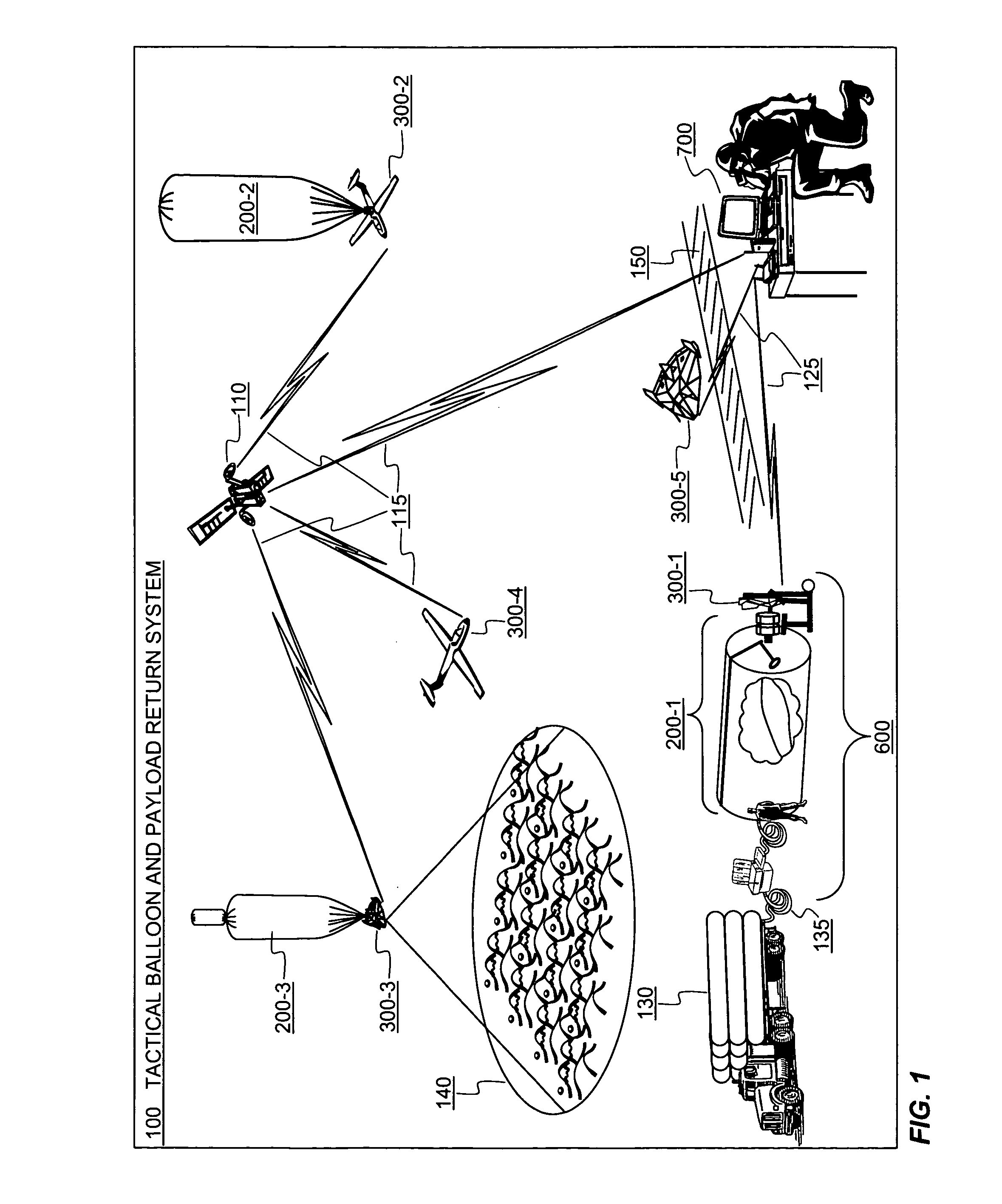
[0029]The high-level diagram of FIG. 1 shows components of an embodiment of the present invention and their relationships to one another in an example operational context. Tactical Balloon and Payload Return System 100 comprises primarily a lighter-than-air vehicle for low-energy lift to altitude, Tactical Balloon 200; an aerodynamic winged vehicle for payload containment and return, Payload Return Vehicle (PRV) 300; a set of equipment that facilitates launching the flight items, Tactical Launch Apparatus 600; and a set of equipment that facilitates monitoring and controlling the flight items, Ground-Based Control Station 700. Each of these components is detailed in subsequent paragraphs.

[0030]Three instances of Tactical Balloon 200 are shown, representing three distinct states of deployment. Tactical Balloon 200-1 is in the pre-launch configuration, coupled closely with the components of Launch Apparatus 600. Gas Supply 130, depicted as a truck hauling large tanks but potentially a...


PUM


Abstract

A system is disclosed whereby a sensor, communication device, or other payload may be lofted to an operational altitude and maintained over an area of interest for some time by a relatively inexpensive and disposable buoyant aircraft, then returned intact to its point of origin or another desired location by a reusable but also relatively inexpensive non-buoyant aircraft. Automatic unpiloted control is used for all stages of flight, including ascent, loiter, return, and landing Specialized equipment can be provided to simplify launch procedures, reducing the number of personnel required to operate the system.

Description

[0001]The present application claims benefit of U.S. Provisional Application No. 61 / 064,297 filed, Feb. 26, 2008, which is hereby incorporated by reference in its entirety.TECHNICAL FIELD OF THE INVENTION[0002]This invention pertains in general to aeronautical platforms for carrying command, control, communications, computing, intelligence, surveillance, and reconnaissance (C4ISR) capabilities to near-space (altitudes between 65,000 feet and 120,000 feet), and returning same to the point of launch or another desired location. The invention pertains in particular to a novel hybrid near-space platform that combines a lighter-than-air vehicle for lift and loiter with a winged aerodynamic vehicle for payload return. The invention further pertains in particular to ground support and launch equipment associated with such platforms.BACKGROUND OF THE INVENTION[0003]Balloon systems have been used for decades to carry atmospheric sensors, surveillance equipment, and communications gear to var...

Claims


Application Information

Patent Timeline
Patent Type & Authority Patents(United States)
IPC IPC(8): B64F1/04
CPCB64C39/024B64C2201/021B64C2201/022B64C2201/082B64C2201/127B64U10/30B64U70/20B64U10/25B64U2101/30
Inventor LACHENMEIER, TIMOTHY T.
Owner LACHENMEIER TIMOTHY T
Why Eureka
Try Eureka