Pressure cast concrete or mortar lined steel pipes and methods of making the same

a technology of pressure cast concrete and steel pipes, which is applied in the field of pressure cast concrete or mortar lined steel pipes, can solve the problems of limiting the allowable design stress, cracks, and limited allowable strain in the concrete or mortar lining, and achieves the effect of saving raw material costs and reducing diameter

Active Publication Date: 2011-12-06
NWPC LLC
View PDF6 Cites 6 Cited by
  • Summary
  • Abstract
  • Description
  • Claims
  • Application Information

AI Technical Summary

Benefits of technology

[0012]In an example embodiment, the mold assembly comprises a cylindrical metal shell that defines the metal outer portion of the pipe, a base member that is operatively connected with a bottom portion of the metal shell, and a top member that is operatively connected with a top portion of the metal shell. An inner mold member is positioned concentrically inwardly of the metal shell. An annular concrete or mortar chamber is formed between the metal shell and inner mold member for accommodating a volume of a concrete or mortar composition therein. In an example embodiment, the inner mold member is capable of reducing in diameter to accommodate removal of the pressure cast lined pipe from the mold after formation. The assembly further comprises a means for introducing a fluid pressurizing medium, such as water, into the mold and onto a surface of the concrete or mortar composition to cause the composition to expand the metal shell.
[0013]Pressure cast lined steel pipes of this invention provide a desired level of pipe stiffness and internal corrosion resistance that matches the typical minimum 50 year service life offered by conventional PCCP or concrete lined steel pipe. Further, such pipes of this invention are capable of providing a desired degree of protection from external corrosion and cathodic interference. Still further, pipes of this invention can be formed having a reduced metal shell or steel pipe wall thickness, thereby resulting in a desired savings of raw material costs.

Problems solved by technology

The reason for limiting the allowable design stress in such pipe is the limited allowable strain in the concrete or mortar lining.
A higher steel stress will crack the concrete or mortar lining under pressure, causing deleterious cracks to form, adversely affecting the lining's performance, and creating the potential for the lining to fail or otherwise fall out of the inside of the steel pipe.
However, no currently available polymer coating can be guaranteed or expected to last 50 years in water service without some form of periodic maintenance, typically at approximately 15 year intervals.
It is not practical to take such coated steel water pipes, e.g., when used as a water main or the like, out of service to sandblast and recoat the lining every 15 or so years for maintenance purposes.
A second limitation for concrete lined steel water pipe is the engineering consideration and need to have a diameter to thickness ratio of around 240, and preferably less than about 220.
In poor soil conditions, the pipe is also vulnerable to collapse or over deflection if not stiffened by increased liner thickness, steel pipe wall thickness, attached stiffeners, or the expensive importation of more stable bedding materials.
One of the problems, however, with PCCP is the difficulty in protecting the high strength prestressing wires from corrosive environments when the pipe is placed into service, and the potential susceptibility of such wires to hydrogen embrittlement if excessive levels of cathodic protection are applied.
The ability to easily cathodically protect the prestressing wire is further complicated by the low dielectric strength of the typical mortar coating that is placed over the prestressing wires to protect them from corrosion.
While the use of such a polymer coating makes it easier to cathodically protect the steel prestressing wires, it does so at an additional cost in terms of both manufacturing steps and in terms of raw material cost.
As the underground utility complex of pipes and surface or subsurface transit systems in typical major cities have increased over the years, another problem has arisen from “cathodic interference” or stray ground currents caused by nearby steel pipelines under cathodic protection for exterior corrosion, and caused by DC powdered transit systems.
These new pipes may be cathodically protected, and the stray ground currents introduced from the cathodic protection can cause corrosive currents in the PCCP.
Although this is an effective approach for controlling pipe corrosion, it is costly.
However, two major problems exist with this method of making pipe.
A first problem relates to the difficulty in perfectly sealing the ends of the concrete core to the steel pipe during the pressure grouting operation.
A second problem involves how to apply and maintain pressure to the grout during the cure of the grout, especially if minor leakage of the grout occurs at the seals between the steel pipe and concrete core while the grout is curing.
This will mean the grout pump will have to be active during the curing operation in order to make up for leakage, which leaves the potential for the grout to cure in the pump, both ruining the pump and resulting in pipe having an insufficient level of prestress.

Method used


Image

  • Pressure cast concrete or mortar lined steel pipes and methods of making the same
  • Pressure cast concrete or mortar lined steel pipes and methods of making the same
  • Pressure cast concrete or mortar lined steel pipes and methods of making the same

Examples


example

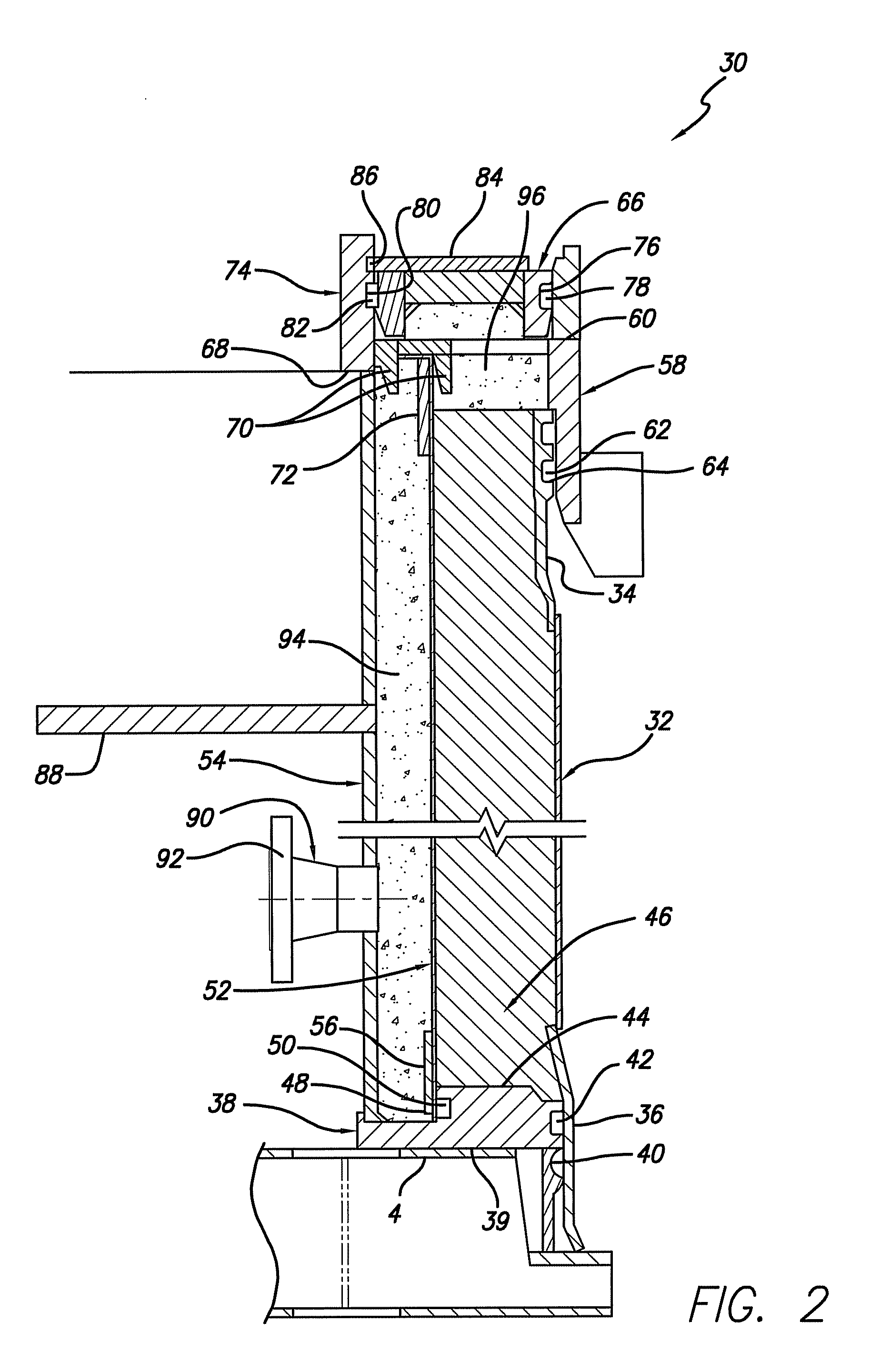
[0100]a PCSP was formed using the assembly illustrated in FIG. 2, having an metal shell inside diameter of approximately 92 inches, by delivering a concrete composition comprising approximately 750 lbs cement (Type I / II), 1490 lbs coarse aggregate, 1400 lbs sand, 319 lbs water, 60 fl oz high range water reducing admixture (Glenium 7700), 10 fl oz viscosity-modifying admixture (VMA 538), and comprising a small amount of air voids (2.5%), wherein the total weight of the composition was approximately 3959 lbs. If desired, a portion (15 to 20 percent by weight) of the cement component disclosed in the above composition can be replaced by an expansive agent, such as Komponent from CTS Cement Manufacturing Corp, to compensate for the shrinkage due to drying and creep. This composition was delivered into the concrete or mortar mold chamber. The collapsible inner mold member is positioned so that the inside diameter of the resulting cured concrete liner is approximately 84 inches. The metal...


PUM

PropertyMeasurementUnit
thicknessaaaaaaaaaa
thicknessaaaaaaaaaa
wall thicknessaaaaaaaaaa

Abstract

Pressure cast lined steel pipes comprise an annular concrete or mortar liner along an inside diameter, and a metal shell surrounding the liner, wherein the liner is in direct contact with the metal shell. The wall thickness of the liner can be from 10 to 50 times the thickness of the metal shell. The pipe may be coated with a dielectric material. A mold assembly used to form the pipe includes an annular concrete or mortar composition chamber formed between the metal shell and an inner mold member. Pressurized water is used in the mold assembly to pressurize the concrete or mortar composition and exert a desired pressure force onto the metal shell while the composition cures in the mold. Once a desired degree of cure is achieved, the pressure is removed causing the metal shell to exert a desired compression force onto the cured liner.

Description

FIELD OF THE INVENTION[0001]This invention relates to concrete or mortar lined steel pipes and, more particularly, to pressure-cast concrete or mortar lined steel pipes that are made using methods that permit the simultaneous curing and prestressing of the pipe to thereby increase allowable design stress in the steel while maintaining manufacturing efficiency and reducing manufacturing costs.BACKGROUND OF THE INVENTION[0002]Conventional concrete lined steel water pipe, e.g., large diameter pipe, is currently designed to a maximum working stress in the steel of around 21,000 psi. The reason for limiting the allowable design stress in such pipe is the limited allowable strain in the concrete or mortar lining. A higher steel stress will crack the concrete or mortar lining under pressure, causing deleterious cracks to form, adversely affecting the lining's performance, and creating the potential for the lining to fail or otherwise fall out of the inside of the steel pipe.[0003]The use o...

Claims


Application Information

Patent Timeline
Patent Type & Authority Patents(United States)
IPC IPC(8): F16L9/00B28B5/00
CPCB28B3/003B28B19/0023F16L9/02F16L58/06F16L9/085Y10T29/5185Y10S138/05Y10T29/4998
Inventor FRIEDRICH, RALPH S.SHENG, QIZHONGKUBAT, PAUL
Owner NWPC LLC
Why Eureka
Try Eureka