Electrolytic microfinishing of metallic workpieces

a technology of electrolytic microfinishing and workpieces, which is applied in the direction of manufacturing tools, electric circuits, electric circuits, etc., can solve the problems of poor microfinishing effect, low microfinishing efficiency, and inability to achieve the effect of microfinishing, reducing the cost of the microfinishing process, and significantly reducing the overall cycle tim

Inactive Publication Date: 2011-12-06
THIELENHAUS MICROFINISH
View PDF50 Cites 1 Cited by
  • Summary
  • Abstract
  • Description
  • Claims
  • Application Information

AI Technical Summary

Benefits of technology

[0022]The invention relates to an improved microfinishing process for the use on component parts for the automotive, diesel engine, aerospace, hydraulic and medical devices, and many other precision industries. This electrolytic microfinishing process uses solid abrasives to machine geometric accuracies by generating the form which improves or creates surface finishes not previously achieved by any other machining method known to date. The electrolytic microfinishing process allows faster material removal, better surface finishes, burr-free surfaces, significantly reduced holding or contact pressure between the tool and workpiece results in reduced tool wear, reduced cycle time by over 50% of the conventional microfinishing process while creating an abrasive free finished surface. Electrolytic microfinishing machines closely resemble conventional microfinish machines in both appearance and to some degree operation. For example, the tool in all cases, looks just like the conventional abrasive stone, except that the stone contains electrically conductive bonding material to hold the abrasive together. The electrolyte that is used is introduced to the wheel in much the same manner as conventional coolants used in any machining operation. A housing is provided to contain the electrolytic solution. The installation also requires a power supply, a very simple pumping station with the appropriate filtration system to provide the electrolyte from an electrolyte reservoir to the workpiece to be microfinished. Since both the work spindle and tool spindle have been electrically isolated, in operation, the workpiece becomes a positive pole and the tool becomes a negative pole in the direct current circuit. When the current source is switched on, the material of the workpiece is decomposed or dissolved by the electrolyte, which is pumped between the rotating surfaces of the tool and workpiece. The rotating tool near the workpiece results in the tool carrying the electrolyte into the cut which brings about the electrochemical action on the workpiece. Metal removal is largely brought about by non-mechanical action, since the contact pressure between the tool and the workpiece is only a fraction of the pressure used in conventional microfinishing. Thus, the need for frequent dressing of the tool is eliminated. The metal removal rate is largely governed by the amount of electric power and electrolyte applied, regardless of the material's hardness. Because of the dissolving action and relative absence of both heat and tool contact, the electrolytic microfinishing process is ideal for fast stock removal of parts that cannot stand thermal machining damage, as well as result in extremely smooth surface finishes. By eliminating contact between the tool and workpiece, the risk of transfer of abrasive particles from the tool to the workpiece is completely eliminated, thereby ensuring an abrasive-free microfinished surface on the workpiece. This invention is ideally practiced as a final machining step on a workpiece with a surface to be finished by reducing or eliminating one or more metal cutting or machining steps, i.e., turning and / or grinding of a conventional nature. A programmable microfinish process controller monitors the various process parameters using sensors to obtain the optimum performance from each of the process elements.
[0023]It is the principle object of the invention to provide a microfinishing apparatus and method which is capable of appreciably reducing the cost of the microfinishing process for a given degree of precision of the overall operation. Accordingly, it is an object of the present invention to provide a method of producing a metallic or conductive workpiece with a microfinished surface that is free of any abrasive particles embedded into the microfinish surface.
[0024]It is a further object of the invention to provide an electrolytic microfinishing process resulting in faster material removal thereby significantly reducing the cycle time of the overall operation.
[0026]It is a further object of the invention to provide an electrolytic microfinishing process which significantly reduces the number of steps required in order to obtain stock removal and smooth surface characteristics superior to those achievable by any conventional finishing and / or machining process know to date.
[0028]It is still a further object of the invention to provide an electrolytic microfinishing process that significantly reduces the overall cost of microfinishing by closely monitoring the parameters of the process and precisely modulate the process parameters to guarantee that optimal levels of current is provided to the workpiece at all times to obtain a given surface smoothness characteristic.

Problems solved by technology

In spite of the many advantages, electrolytic decomposition or grinding may provide little or no success that has been achieved in applying the principle of electrolytic erosion to the microfinishing process.
In many cases the derived feed rate may be extremely small.
During this second stage, the rough abrasive tool surface continues to cut and wear.
This results in a lower feed rate and consequently decreases wear.
Flat and complete spherical surfaces are the easiest shapes to achieve a very accurate, uniform geometry and finish, while the partial / conical shape proves to be the most difficult.
Further, the use of a tool with a surface covered with abrasive particles can result in the embedding of abrasive particles into the surface of the article being processed, and this factor can detract from the surface quality of the processed workpiece when an abrasive coated tool is used as a final step in the electrochemical machining process.

Method used


Image

  • Electrolytic microfinishing of metallic workpieces
  • Electrolytic microfinishing of metallic workpieces
  • Electrolytic microfinishing of metallic workpieces

Examples


Embodiment Construction

[0039]The following detailed description discloses a microfinishing process. The use of the term microfinishing is intended to include what is sometimes referred to as superfinishing, mirror finishing, lapping, honing, fine grinding or just plain finishing. In fact, microfinishing is used to describe any machining process which results in superlative surface smoothness characteristics.

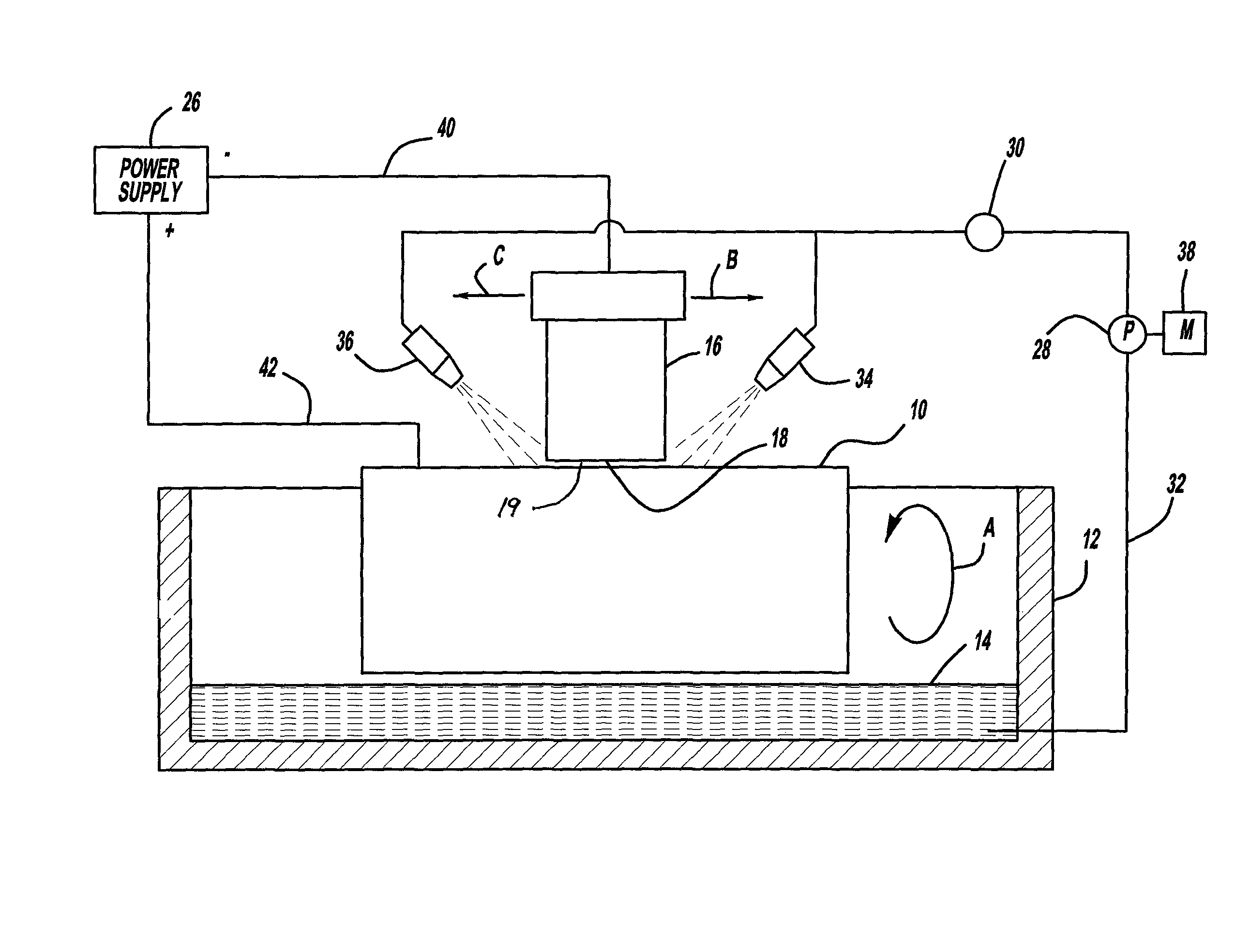
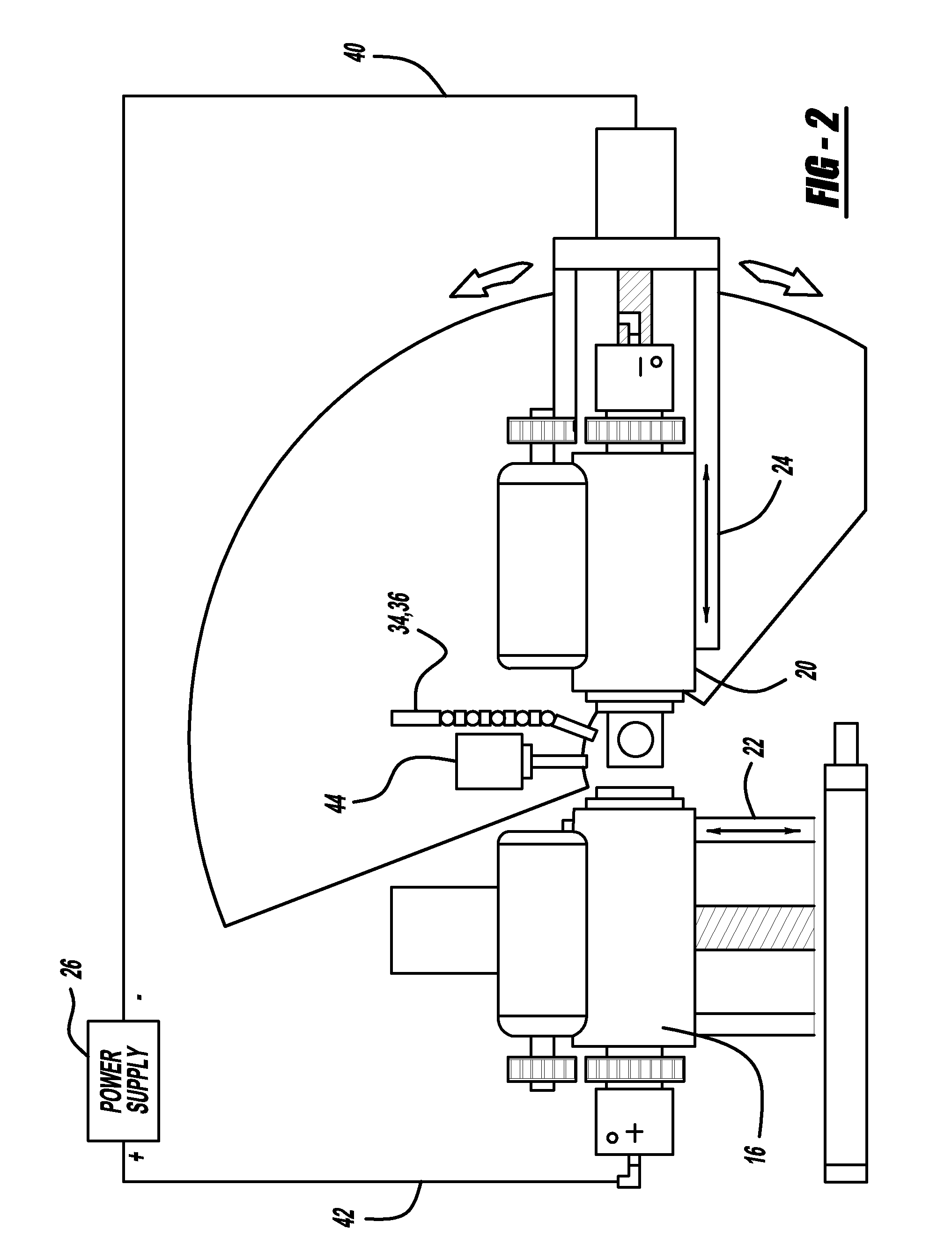
[0040]With reference to FIGS. 2-8a, a metallic or conductive workpiece 10 to be provided with a microfinished outer surface or at least a portion of a microfinished outer surface is positioned within the housing 12 that contains an electrolytic solution 14. The workpiece 10 is mounted on a work spindle 16 which has been built to ensure the possibility of delivering current with the highest precision. Accordingly, a work spindle 16 is utilized to eliminate earlier prior art serious limitations on their ability to consistently deliver current, given the mechanical constraints due to the high speed rotati...


PUM

PropertyMeasurementUnit
current densityaaaaaaaaaa
voltageaaaaaaaaaa

Abstract

The invention is an electrolytic microfinishing process which utilizes a conductive tool as a cathode and a conductive workpiece as an anode both connected to a power supply. Electrolytic fluid is pumped between the tool and workpiece, creating a decomposition of the workpiece surface allowing the surface of the workpiece to be removed or wiped away by the interaction of the flowing electrolyte and rotation of the tool without generating any heat at a rate significantly faster than any other known machining process. The tool has no contact with the workpiece and accordingly, requires very low clamping loads to hold the workpiece in the spindle during the finishing operation. Due to the low clamping loads, the distortion of the workpiece is completely eliminated. Modulating the power supply during the work cycle allows the use of a single tool for both roughing and finishing as a continuous cycle to significantly provide surface finishes previously unobtainable.

Description

CROSS REFERENCES TO RELATED APPLICATIONS[0001]This application claims the benefit of provisional U.S. Patent Application Ser. No. 60 / 678,854, filed on May 6, 2005.FEDERALLY SPONSORED RESEARCH OR DEVELOPMENT[0002]Not ApplicableREFERENCE TO MICROFICHE APPENDIX[0003]Not ApplicableBACKGROUND OF THE INVENTION[0004]1. Field of the Invention[0005]The invention relates in general to a method and apparatus of electrolytically microfinishing metallic workpieces. More particularly, this invention has specific reference to the application of electrolytic machining to a microfinishing process with a view to decrease considerably, the cycle time of finishing the workpiece to be treated while reducing appreciably, the cost of the microfinishing operation for a given degree of precision.[0006]2. Description of the Related Art[0007]There are two well know methods of machining work pieces using electrolytic cutting.[0008]The first is electrochemical machining (ECM) which is done by using a cathode ha...

Claims


Application Information

Patent Timeline
Patent Type & Authority Patents(United States)
IPC IPC(8): B23H3/00
CPCB23H3/00B23H5/08
Inventor BECKER, MANFRED G.
Owner THIELENHAUS MICROFINISH
Why Eureka
Try Eureka