Method of manufacturing large dish reflectors for a solar concentrator apparatus

a technology of solar concentrator and reflector, which is applied in the direction of glass tempering apparatus, glass reforming apparatus, glass forming apparatus, etc., can solve the problems of limited thermal conversion efficiency, rising sea level enough to put many coastal cities under water, and the climate and the world in which we live will suffer catastrophic consequences, etc., to minimize the cost of the supporting mechanical structure used, maximize the effect of stiffness and strength

Active Publication Date: 2011-12-27
THE ARIZONA BOARD OF REGENTS ON BEHALF OF THE UNIV OF ARIZONA
View PDF35 Cites 25 Cited by
  • Summary
  • Abstract
  • Description
  • Claims
  • Application Information

AI Technical Summary

Benefits of technology

[0016]Concentration of solar radiation in accordance with the present invention is made by a rigidly co-aligned array of intermediate size dish reflectors pointed substantially directly at the sun by a two-axis tracker. Each intermediate size dish reflector powers a compact converter at the focus of the reflector. An advantage of the present invention is a clean separation of compact energy conversion units from a plurality of relatively simple but inherently large energy collection elements. In this way, aspects of mass production, transport assembly, upgrade and maintenance of the three major components, i.e., the reflector dishes, the trackers, and the conversion units, can be separately optimized. In accordance with the present invention, optical throughput is maximized by using conversion units whose cross sectional area is much less that the area of the reflector dish needed to power them.
[0017]During the day, the sun rises in the east, moves across the sky, and sets in the west. There is a need to adjust the orientation of reflectors so that they point in the direction of the sun as it moves across the sky. In order to make a solar generation system that is cost competitive, it is important to minimize the cost of the supporting mechanical structure used to track the sun. This is achieved in accordance with the present invention by supporting multiple reflector and converter units in a rigid, lightweight spaceframe. A spaceframe in accordance with the present invention is a rigid, lightweight, open truss structure that maximizes stiffness and strength while minimizing mass per unit area of collected light. The open truss structure extends in three dimensions to achieve both high stiffness against bending by gravity and wind, and high strength to survive occasional very high winds. Two dimensions extend across the area of sunlight collected, and the third dimension extends in the perpendicular direction, along the optical axis linking the reflector units below and the converter units above.
[0018]In accordance with the present invention, the cost of the reflectors and tracker is further minimized by use of inexpensive materials, such as glass and steel. A feature of the invention is that individual reflectors take the form of a large glass monolith, as opposed to an array of discrete abutting segments. Monolithic construction simplifies glass reflector manufacturing and integration, and minimizes the number of support points per unit area for a given glass thickness and mass per unit area (areal density).
[0019]One feature of the present invention is that the primary dish optics have optical quality which results in only moderate degradation at the concentration limit set by the diameter of the sun's disc, with the capability of delivering solar radiation at high concentration, preferably 10,000 times, at the direct focus of a generally paraboloidal reflector of short focal ratio. Such high concentration is not always required at the actual point of conversion, but along with accurate tracking of the rigid spaceframe structure, this level of concentration provides maximum flexibility for the design of conversion units to exploit the advantages of the solar concentration.
[0020]It is another feature of the present invention that the aspect ratio of the array of reflectors carried by each two-axis tracker is wide and low. The horizontal extension provided in the present preferred design minimizes shadowing at low sun elevation by adjacent units in a field of multiple units, thus maximizing land use. This preferred design also minimizes wind loading.
[0021]A feature of the present invention is that the drives have a high mechanical advantage, which advantageously minimizes parasitic loads from drive motors. An additional feature of the present invention is that the drive elements are applied at a large radius, which advantageously minimizes drive forces and mass of the drive components.SUMMARY OF THE INVENTION

Problems solved by technology

Many experts believe that if something is not done soon to slow or even reverse this accumulation, our climate and the world in which we live will suffer catastrophic consequences.
Experts predict that a rise in global temperatures of just a few degrees will melt polar ice, and result in a rise of sea levels enough to put many coastal cities under water.
The efficiency of thermal conversion is limited by the second law of thermodynamics, which requires high temperature and hence highly concentrated light for high conversion efficiency.
Thus, in the past, significant effort and attention has been given to the problem of converting solar energy at high concentration, but the results have not been altogether satisfactory.
Despite the availability of solar conversion devices that operate more efficiently in highly concentrated light, high concentration solar energy systems have not yet become a major factor in global solar electricity production.
A significant drawback to prior attempts at high concentration systems has been the high cost of the opto-mechanical systems required to provide highly concentrated light to solar conversion devices.
Prior efforts have not been cost competitive, in part, because of the unfavorable scale sizes of the optical concentrators.
These prior attempts often involved the use of particular conversion devices requiring input of concentrated sunlight at either very low levels or very high levels of power, and such power requirements led for the most part to either very small or very large optical apertures for the sunlight concentrators.
This design approach failed to adequately minimize the cost per unit of generated electricity (or other form of energy).
This led to inefficiencies and high costs.
Arrays of large numbers of small units with small optical concentrators were expensive to manufacture, assemble and transport, because they were both large and complex, with many small optical and electrical and thermal components arrayed over a large area.
This design approach added significantly to the cost of a tracker to be used in such systems, and failed to achieve adequately minimized cost per unit of generated electricity (or other form of energy).
Large optics concentrating in two dimensions to meet these requirements led to inefficiencies.
Both of these design approaches were sub-optimal in terms of minimizing the concentrator system cost per watt delivered, and failed to adequately minimize the cost per unit of generated electricity (or other form of energy).
For large single dishes, structural complexity and both mass and cost per unit area all rise with dish area.
A composite large reflector assembled in this manner tended to be heavy and expensive to manufacture and assemble.
A further disadvantage of large round dishes was relatively high wind load per unit area, which required heavier and more expensive support structure to resist wind loading.
A significant disadvantage to this approach was the inefficient use of trackers carrying a given reflector area.
This inefficiency resulted because the sunlight incident on many of the heliostat mirrors was at angles far from normal incidence, thus the daily average of solar power delivered to the power tower was only a fraction of what could be captured if each mirror could be tracked to face the sun.
Another disadvantage was the mechanical complexity of many small two-axis trackers for heliostats.
A further difficulty with many prior solar concentrator systems has been the special demand placed on their two-axis trackers.
Typical designs were not balanced about the elevation axis, and therefore typically suffered from high, concentrated drive loads and consequently required heavy drive mechanics.
Of course, heavy drive mechanics increased the cost of such systems, and in solar energy systems, cost is a critical factor that separates success from failure.
Large, high concentration dishes for thermal conversion were often especially compromised in their mechanical structure by a large radial opening for an arm to support a fluid heater, engine or turbine and electromagnetic generator at the focus.
Solar energy systems are unlikely to have a significant impact on reducing greenhouse gasses in the atmosphere until electricity can be generated using solar energy at a cost that is competitive with electricity generated by burning fossil fuels.
In fact, cost cannot be over emphasized, because it is so important that cost alone can make the difference between success and failure.
Cost is of critical importance—otherwise solar conversion systems are unlikely to displace a large percentage of conventional electrical generation plants that generate electricity by burning fossil fuels.

Method used


Image

  • Method of manufacturing large dish reflectors for a solar concentrator apparatus
  • Method of manufacturing large dish reflectors for a solar concentrator apparatus
  • Method of manufacturing large dish reflectors for a solar concentrator apparatus

Examples


Embodiment Construction

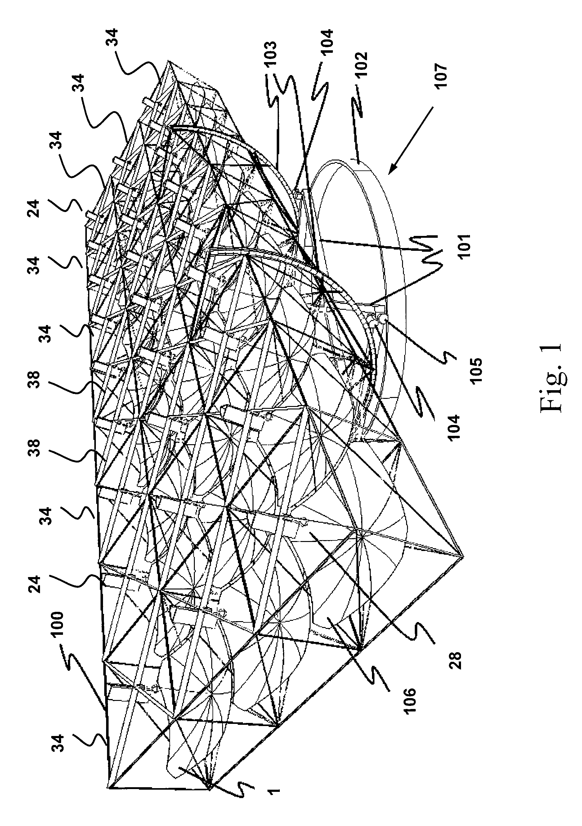
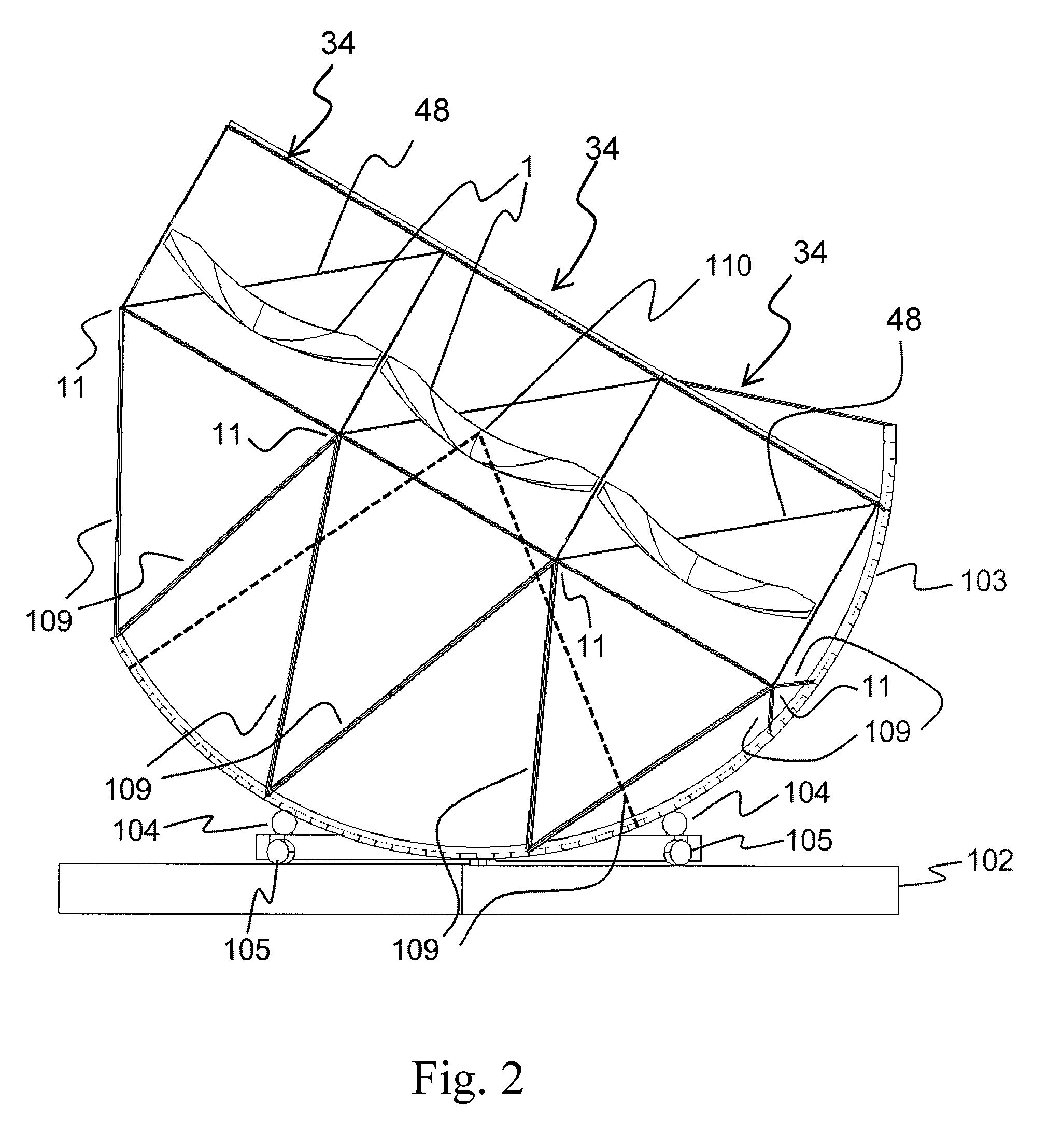
[0085]FIG. 1, FIG. 2 and FIG. 3 illustrate a presently preferred embodiment of the invention comprising a plurality of unit reflector cells 34 with large paraboloidal reflectors 1 held co-axial in a rigid framework 100. In the illustrated example, an array of twenty-seven unit reflector cells 34 is shown in a rectangular grid that is three rows by nine columns, but other configurations and arrangements may be used with a plurality of concentrators arranged in various other configurations. It is desirable to have the capability of pointing the array of reflectors 1 at the sun as the sun moves across the sky during the day. In order to accomplish this, the common axis of the reflectors 1 is oriented to the sun by a two-axis tracker 107. In this exemplar embodiment, a flat truck 101 turns on a circular track 102 on the ground to provide azimuthal rotation of the framework 100 supporting the paraboloidal reflectors 1. Elevation motion is provided by two C-rings 103 attached to the rigid...


PUM

PropertyMeasurementUnit
thicknessaaaaaaaaaa
reflectivityaaaaaaaaaa
input power levelaaaaaaaaaa

Abstract

A method of manufacturing monolithic glass reflectors for concentrating sunlight in a solar energy system is disclosed. The method of manufacturing allows large monolithic glass reflectors to be made from float glass in order to realize significant cost savings on the total system cost for a solar energy system. The method of manufacture includes steps of heating a sheet of float glass positioned over a concave mold until the sheet of glass sags and stretches to conform to the shape of the mold. The edges of the dish-shaped glass are rolled for structural stiffening around the periphery. The dish-shaped glass is then silvered to create a dish-shaped mirror that reflects solar radiation to a focus. The surface of the mold that contacts the float glass preferably has a grooved surface profile comprising a plurality of cusps and concave valleys. This grooved profile minimizes the contact area and marring of the specular glass surface, reduces parasitic heat transfer into the mold and increases mold lifetime. The disclosed method of manufacture is capable of high production rates sufficiently fast to accommodate the output of a conventional float glass production line so that monolithic glass reflectors can be produced as quickly as a float glass production can make sheets of float glass to be used in the process.

Description

CROSS-REFERENCE TO RELATED APPLICATIONS[0001]This application is based upon and claims the benefit of the filing date of Provisional Patent Application Ser. No. 61 / 127,298, filed May 12, 2008, entitled “Solar Photovoltaic Generator,” the entire disclosure of which is incorporated herein by reference. This application discloses subject matter related to application Ser. No. 12 / 436,016, filed contemporaneously herewith, entitled “Photovoltaic Generator with a Spherical Imaging Lens for Use with a Paraboloidal Solar Reflector,” by Roger P. Angel, the entire disclosure of which is incorporated herein by reference. This application also discloses subject matter related to application Ser. No. 12 / 436,001, filed contemporaneously herewith, entitled “Solar Concentrator Apparatus with Large, Multiple, Co-Axial Dish Reflectors,” by Roger P. Angel and Warren B. Davison, the entire disclosure of which is incorporated herein by reference.[0002]This invention was funded by the United States Gover...

Claims


Application Information

Patent Timeline
Patent Type & Authority Patents(United States)
IPC IPC(8): C03B23/025F24S23/30F24S23/70F24S23/71F24S50/20
CPCC03B23/0256H01L31/0547C03B23/0357F24J2/08F24J2/1057F24J2/12F24J2/38F24J2/542C03B23/0258C03B23/0355F24J2/523F24J2/5233F24J2002/5458F24J2002/5475F24J2002/5479Y02E10/42Y02E10/47Y02E10/52F24J2002/0084H02S40/22F24S2030/145F24S2020/16F24S25/13F24S50/20F24S2030/133F24S25/10F24S30/452F24S2030/14F24S23/82F24S23/30F24S23/71C03B23/0352H01L31/052H01L31/054F24S23/70C03B23/035Y02E10/40
Inventor ANGEL, ROGER POLBERT, BLAIN H
Owner THE ARIZONA BOARD OF REGENTS ON BEHALF OF THE UNIV OF ARIZONA
Why Eureka
Try Eureka