Thermal shield at casing joint

a shielding and casing technology, applied in the direction of machines/engines, stators, liquid fuel engines, etc., can solve problems such as the rotation of the rotor, and achieve the effect of reducing the amount of heat transfer and reducing the thermal stress induced

Inactive Publication Date: 2012-01-10
SIEMENS ENERGY INC
View PDF15 Cites 25 Cited by
  • Summary
  • Abstract
  • Description
  • Claims
  • Application Information

AI Technical Summary

Benefits of technology

[0005]In accordance with a first aspect of the present invention, a thermal shield is provided for reducing thermal stress induced proximate to a first joint formed between adjacent engine casing components in a gas turbine engine. The thermal shield comprises a cover structure and a thermally insulating layer. The cover structure covers a radially inner portion of at least one of the engine casing components and is disposed proximate to the first joint. The cover structure is attached to a radially inner side of the respective engine casing component so as to limit exposure of the covered inner portion of the respective engine casing component to hot gases in an interior volume defined by the engine casing components. The thermally insulating layer is located between the cover structure and the covered inner portion of the respective engine casing component. The thermally insulating layer effects a reduced amount of heat transfer to the covered inner portion of the respective engine casing component from the hot gases in the interior volume defined by the engine casing components.
[0006]In accordance with a second aspect of the present invention, an engine casing is provided for use in a gas turbine engine. The engine casing comprises two axially adjacent engine casing structures cooperating to form a substantially cylindrical member defining an interior volume therein. Each engine casing structure is comprised of at least one circumferential engine casing component. A circumferentially extending joint is formed between the engine casing structures. The engine casing further comprises at least one thermal shield for reducing thermal stress induced on a portion of at least one of the engine casing components of the engine casing structures proximate to the circumferentially extending joint. The thermal shield comprises a cover structure for covering a radially inner portion of the at least one of the engine casing components and a thermally insulating layer. The cover structure is disposed proximate to the circumferentially extending joint and is attached to a radially inner side of the respective engine casing component so as to limit exposure of the covered inner portion of the respective engine casing component to hot gases in the interior volume defined by the engine casing structures. The thermally insulating layer is located between the cover structure and the covered inner portion of the respective engine casing component. The thermally insulating layer effects a reduced amount of heat transfer to the covered inner portion of the respective engine casing component from the hot gases in the interior volume defined by the engine casing structures.
[0007]In accordance with yet another aspect of the present invention, an engine casing is provided for use in a gas turbine engine. The engine casing comprises a first engine casing structure and a second engine casing structure. The first engine casing structure comprises at least two first engine casing components, wherein an axially extending joint is formed between each of the first engine casing components. The second engine casing structure is disposed axially adjacent to the first engine casing structure and comprises at least two second engine casing components. An axially extending joint is formed between each of the second engine casing components. The first and second engine casing structures cooperate to define an interior volume therein, wherein a circumferentially extending joint is formed between the first and second engine casing structures. Each of the first engine casing components and each of the second engine casing components has a respective thermal shield associated with it for reducing thermal stress induced on the first and second engine casing components. Each of the thermal shields comprises a cover structure for covering a radially inner portion of the respective engine casing component. The cover structure is disposed proximate to the circumferentially extending joint between the first and second engine casing structures and also proximate to the axially extending joint between the respective engine casing components. The cover structure is attached to a radially inner side of the respective engine casing component so as to limit exposure of the covered inner portion of the respective engine casing component to hot gases in the interior volume defined by the engine casing structures.

Problems solved by technology

The expansion of the working gas through the rows of rotating blades and stationary vanes in the turbine assembly results in a transfer of energy from the working gas to the rotating assembly, causing rotation of the rotor.
It has been determined that during engine load-up and shut down procedures, high amounts of stress induced by a thermal gradient may cause cracking of the engine casing proximate to an interface between a compressor / combustor casing and the turbine casing.

Method used


Image

  • Thermal shield at casing joint
  • Thermal shield at casing joint
  • Thermal shield at casing joint

Examples


Embodiment Construction

[0015]In the following detailed description of the preferred embodiments, reference is made to the accompanying drawings that form a part hereof, and in which is shown by way of illustration, and not by way of limitation, specific preferred embodiments in which the invention may be practiced. It is to be understood that other embodiments may be utilized and that changes may be made without departing from the spirit and scope of the present invention.

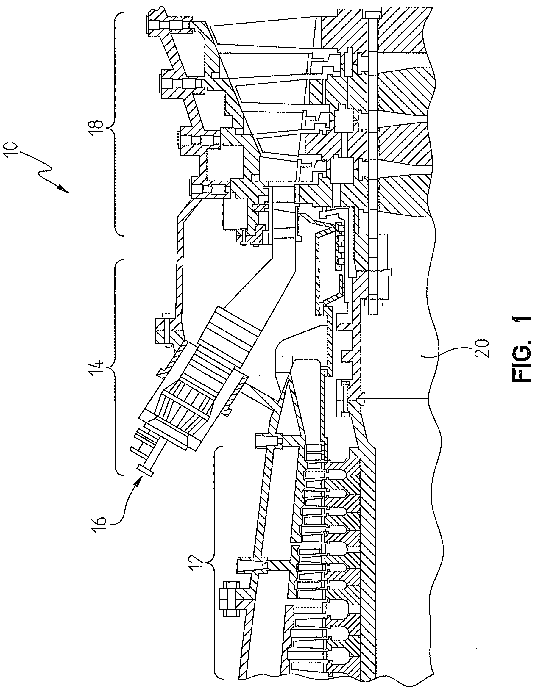
[0016]Referring to FIG. 1, a portion of a gas turbine engine 10 is shown. The engine 10 includes a compressor section 12, a combustion section 14 including a plurality of combustors 16, and a turbine section 18. The compressor section 12 inducts and pressurizes inlet air which is directed to the combustors 16 in the combustion section 14. Upon entering the combustors 16, the compressed air from the compressor section 12 is mixed with a fuel and ignited to produce a high temperature and high velocity combustion gas flowing in a turbulent ...


PUM

PropertyMeasurementUnit
thermal stressaaaaaaaaaa
volumeaaaaaaaaaa
thermally insulatingaaaaaaaaaa

Abstract

A thermal shield for reducing thermal stress induced proximate to a first joint formed between adjacent engine casing components in a gas turbine engine. The thermal shield includes a cover structure for covering a radially inner portion of at least one of the engine casing components. The cover structure is disposed proximate to the first joint and attached to the respective engine casing component so as to limit exposure of a covered inner portion of the engine casing component to hot gases in an interior volume defined by the engine casing components. A thermally insulating layer is disposed between the cover structure and the engine casing component for effecting a reduced amount of heat transfer to the covered inner portion of the engine casing component from the hot gases in the interior volume defined by the engine casing components.

Description

CROSS-REFERENCE TO RELATED APPLICATION[0001]This application claims the benefit of U.S. Provisional Application Ser. No. 61 / 099,678 entitled THERMAL SHIELD AT CASING JOINT, filed Sep. 24, 2008, the entire disclosure of which is incorporated by reference herein.FIELD OF THE INVENTION[0002]The present invention relates to gas turbine engines and, more particularly, to thermal shields for use on engine casing components for reducing thermal stress induced on covered portions of the engine casing components.BACKGROUND OF THE INVENTION[0003]Generally, gas turbine engines have three main sections or assemblies, including a compressor assembly, a combustor assembly, and a turbine assembly. In operation, the compressor assembly compresses ambient air. The compressed air is channeled into the combustor assembly where it is mixed with a fuel and ignites, creating a heated working gas. The heated working gas is expanded through the turbine assembly. The turbine assembly generally includes a ro...

Claims


Application Information

Patent Timeline
Patent Type & Authority Patents(United States)
IPC IPC(8): F01D5/08F01D5/18
CPCF01D25/145F01D25/24F01D25/243F05D2300/614
Inventor CAI, WEIDONGPARKER, DAVID M.
Owner SIEMENS ENERGY INC
Why Eureka
Try Eureka