Erosion- and impact-resistant coatings

a technology of erosion resistance and impact resistance, applied in the direction of wind motors with parallel air flow, wind motors with perpendicular air flow, liquid fuel engine components, etc., can solve the problems of reducing the fuel efficiency of the engine, reducing the efficiency of the compressor, and reducing the efficiency of the engin

a technology of erosion resistance and impact resistance, applied in the direction of wind motors with parallel air flow, wind motors with perpendicular air flow, liquid fuel engine components, etc., can solve the problems of reducing the fuel efficiency of the engine, reducing the efficiency of the compressor, and reducing the efficiency of the engin

US8118561B2Active Publication Date: 2012-02-21GENERAL ELECTRIC CO

Image

  • Erosion- and impact-resistant coatings
  • Erosion- and impact-resistant coatings
  • Erosion- and impact-resistant coatings

Examples


Embodiment Construction

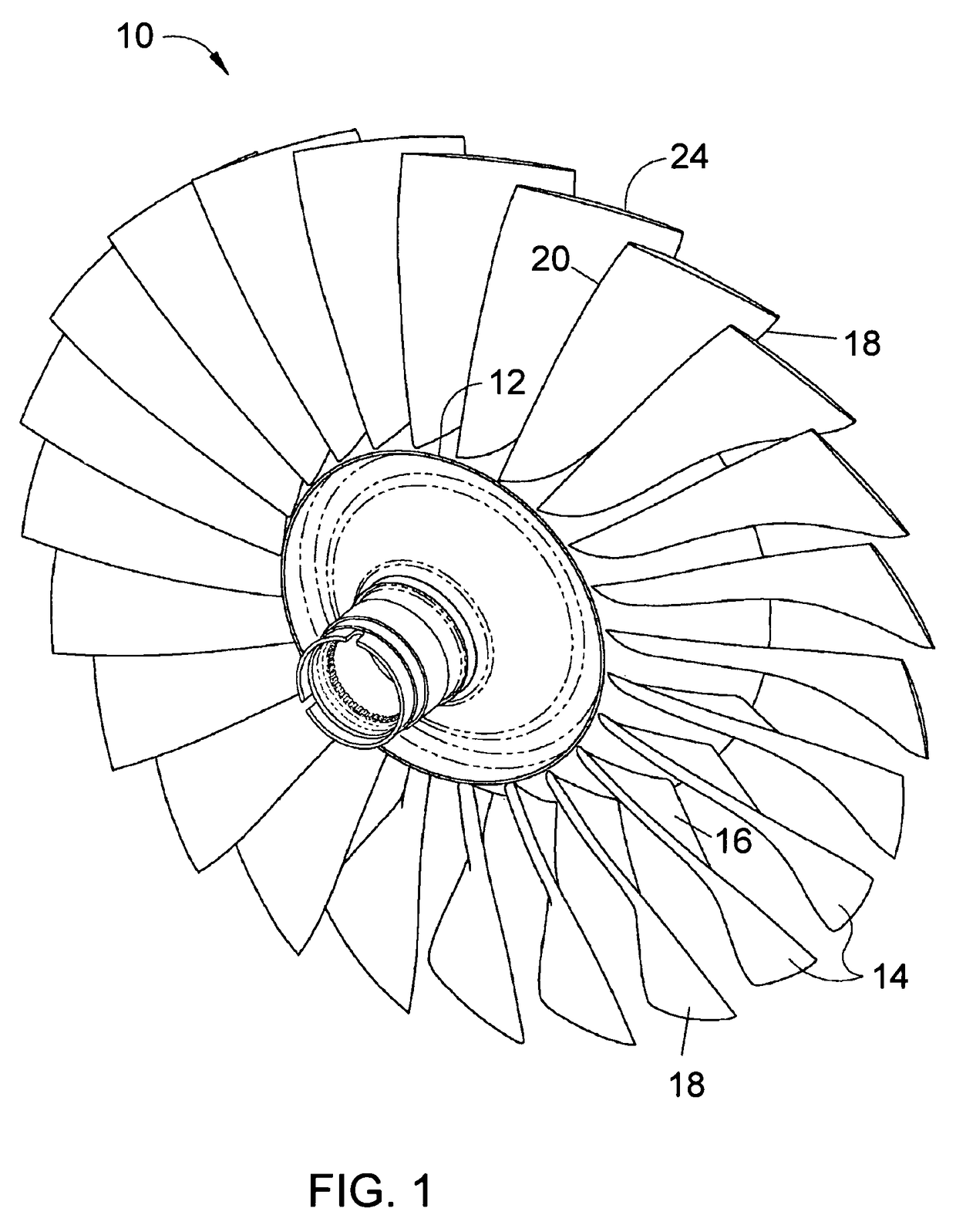
[0016]FIG. 1 represents a blisk 10 of a gas turbine engine. The blisk 10 has a hub 12 from which blades 14 radially extend. The blades 14 can be fabricated integral with the hub 12, yielding what is also referred to as a bladed disk or an integrally bladed rotor. The term “integral” is used to denote multiple components that effectively form a single member without any mechanical discontinuity therebetween, whether the components were originally separately formed and then metallurgically joined or originally formed from a single workpiece. The present invention is particularly well suited for blisks used as low-pressure fans on aircraft gas turbine engines, but is applicable to blisks used in other applications. Furthermore, the invention can be useful for other applications that require impact and erosion resistance, for example, blowers, impellers, splitters, fan components, Pitot tubes, venturi tubes, particle separators, aircraft landing gear components, power transmission compo...


PUM

PropertyMeasurementUnit
thicknessaaaaaaaaaa
thicknessaaaaaaaaaa
thicknessaaaaaaaaaa

Abstract

Erosion- and impact-resistant ceramic coatings suitable for protecting surfaces subjected to collisions with particles, including nominally round particles that typically inflict impact damage and more aggressive irregular-shaped particles that typically inflict erosion damage. The ceramic coating is formed to have one of three compositions: at least one layer of titanium aluminum nitride (TiAlN) having a thickness of about 25 to about 100 micrometers; multiple layers of chromium nitride (CrN) and TiAlN, each layer having a thickness of about 0.2 to about 1.0 micrometers to yield a total coating thickness of at least about 3 micrometers; and at least one layer of titanium silicon carbonitride (TiSiCN) having a thickness of about 15 to about 100 micrometers. The ceramic coating preferably has a total coating thickness of up to about 100 micrometers, and is deposited by a physical vapor deposition process to have a columnar and / or dense microstructure.

Description

CROSS REFERENCE TO RELATED APPLICATIONS[0001]This is a continuation-in-part patent application of U.S. patent application Ser. No. 11 / 656,974, filed Jan. 24, 2007, which is a continuation patent application of Ser. No. 10 / 898,755, filed Jul. 26, 2004, now U.S. Pat. No. 7,186,092. The contents of these prior applications are incorporated herein by reference.BACKGROUND OF THE INVENTION[0002]The present invention generally relates to protective coatings, and more particularly to erosion- and impact-resistant coatings suitable for use in gas turbine engines.[0003]Gas turbines, including gas turbine engines, generally comprise a compressor, a combustor within which a mixture of fuel and air from the compressor is burned to generate combustion gases, and a turbine driven to rotate by the combustion gases leaving the combustor. Both the compressor and turbine utilize blades with airfoils against which air (compressor) or combustion gases (turbine) are directed during operation of the gas t...

Claims


Application Information

Patent Timeline
21 Feb 2012
Publication
US8118561B2
IPC
F01D5/14; F01D5/28
CPC
C23C14/0641; C23C30/00; F01D5/288; F01D25/007; C23C28/04; C23C28/321; C23C28/322; C23C28/34
Inventors
BRUCE, ROBERT WILLIAM; HANIFY, JOHN WILLIAM