Self-aware adaptive power control system and a method for determining the circuit state

a power control system and self-aware technology, applied in the direction of power consumption reduction, pulse technique, instruments, etc., can solve the problems of serious power consumption problems, power gating cells cannot be used as pure switches, and no dynamic power control capability

Active Publication Date: 2012-03-20
NAT CHIAO TUNG UNIV
View PDF8 Cites 8 Cited by
  • Summary
  • Abstract
  • Description
  • Claims
  • Application Information

AI Technical Summary

Benefits of technology

[0019]The self-aware adaptive power control system and the method for determining the circuit state according to the present invention can be applied for all kinds of digital circuits, and control the amount of supply current to effectively reduce to the lowest level, but maintain the normal operation of the circuit; furthermore, the present invention can also control the power of the accommodated circuit, so that it can only consume the least power under various frequencies and achieve the best energy efficiency.

Problems solved by technology

Although the SOC technology can improve the performance, on the other hand, it introduces serious power consumption issues.
However, the power gating cells can only be used as a pure switch, that is, only providing the ON (connected) and OFF (disconnected) states for the carried circuit and power supply.
Except for saving the static power under closed state, there is no capability of dynamic power control.
Therefore, the two conventional techniques will have limited effect on reducing power consumption.
However, the prior art also employs a delay matching circuit theoretically, and has the above-mentioned identical defects.
Moreover, owing to the substantial large power overhead, it could only conduct the overall modulation on the level of entire chip, and could not have the optimization on respective details inside the chip.
Furthermore, when the prior art [2] and [3] is implementing the adaptive or dynamic voltage modulation, it is required of a worst case critical path delay matching circuit, but actually the worst case is seldom occurred.
Besides, the employed control circuit needs additional reference clock and a plurality of flip-flops, so that there is a certain level of area and power overhead, and it could not be applied on the modulation of details.
And, because the time period of reaction variation is always at μs level, they are not suitable for real-time modulation for current high speed circuits.

Method used


Image

  • Self-aware adaptive power control system and a method for determining the circuit state
  • Self-aware adaptive power control system and a method for determining the circuit state
  • Self-aware adaptive power control system and a method for determining the circuit state

Examples


Embodiment Construction

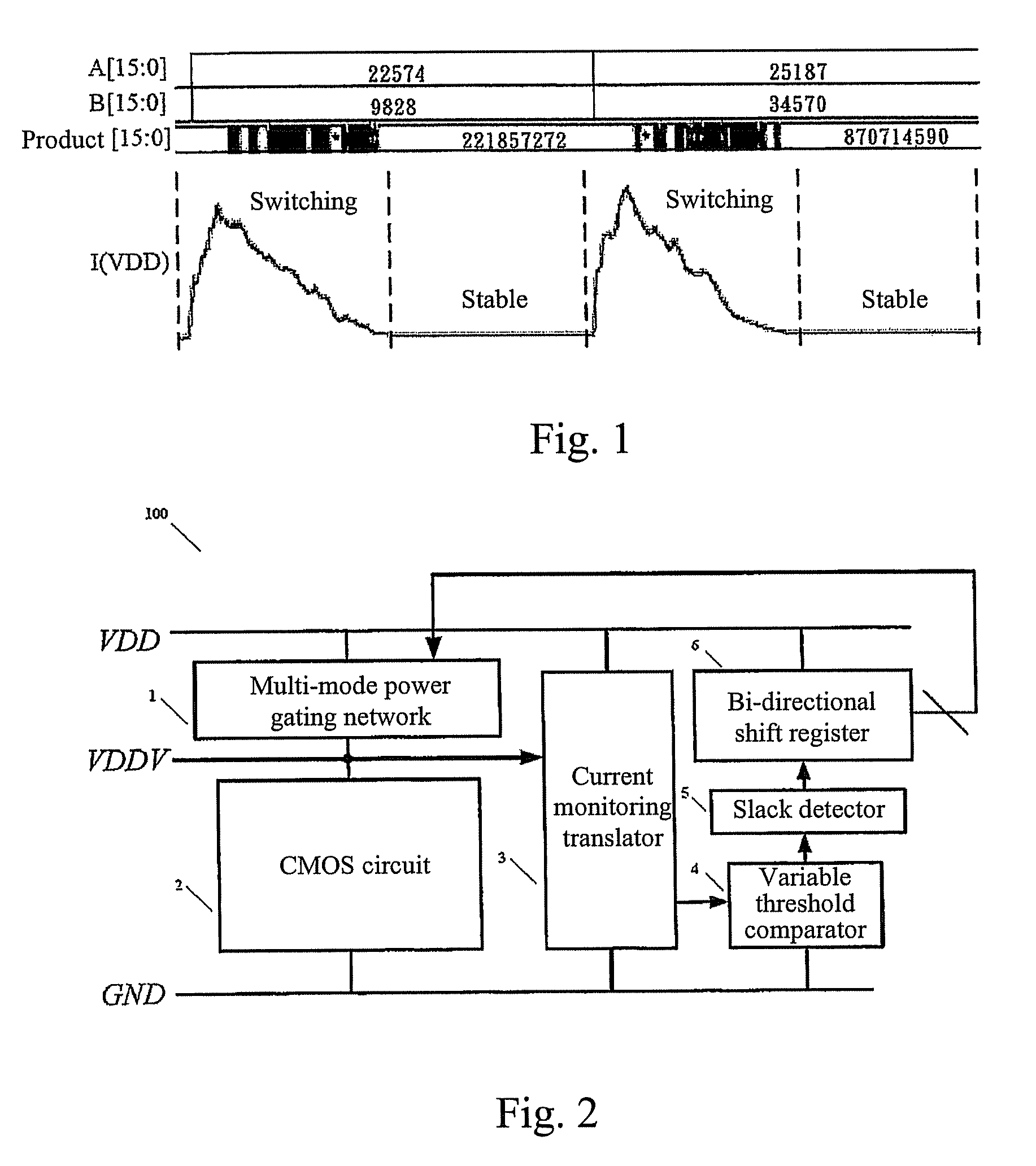
[0027]Referring to FIG. 1, it is a characteristic curve diagram for the current drained from the ideal power supply with a 16-bit multiplier during circuit switching. As observed from the curve in FIG. 1, the multiplier will drain a large amount of current during the switching period, so as to exhibit a sharp momentary current peak. When the multiplication result has been successfully computed, the multiplier, except for the current leakage, will enter a stable state without draining any charge current or discharge current. In other words, in order to have success computing, the steady state period of the circuit should be identified to ensure it will be longer than a specific time. Thus, a current monitoring method has been developed to identify the current amount drained from the power and to determine the circuit state during switching between the switching state and the stable state.

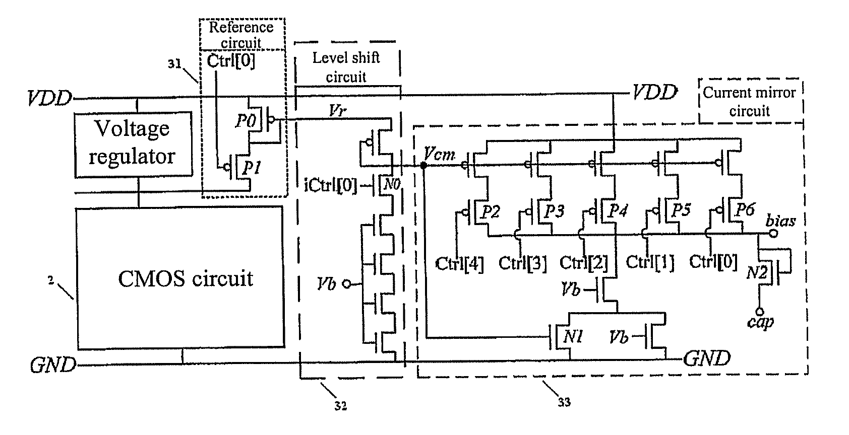
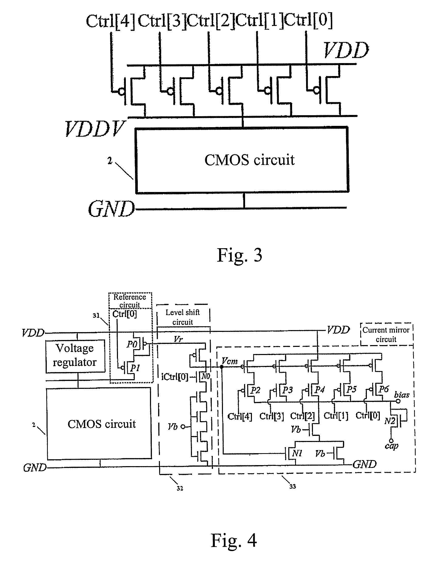
[0028]Referring to FIG. 2, it is a block diagram of a self-aware adaptive power control system ac...


PUM


Abstract

The present invention provides a self-aware power control system and a method for determining the circuit state. The self-aware adaptive power control architecture comprises of a multi-mode power gating network, a current monitoring translator, a variable threshold comparator, a slack detector, and a bi-directional shift register. The multi-mode power gating network controls the amount of supply current and hence the circuit speed. The power gating network can be composed of either N-type MOSFETs for virtual ground insertion or P-type MOSFETs for virtual supply insertion. The number of MOSFETs in the multi-mode power gating network can be configured according to the supply range and step difference of the supply current. Then, by monitoring the current characteristics drained by target circuit, the circuit state can be determined. No delay matching circuit is required. Together with other peripherals, the supply current can be down controlled to a minimum acceptable level. The circuit will use up all available slack. The smaller current implies lower power consumption as well. Furthermore, the present invention is capable of self adaptation to frequency change. To summarize, the present invention can make the circuit consume least power under various frequency achieving best power efficiency.

Description

CROSS-REFERENCE TO RELATED APPLICATIONS[0001]This application claims all benefits accruing under 35 U.S.C. §119 from Taiwanese Patent Application No. 096147398, filed on Dec. 12, 2007 in the Intellectual Property Office Ministry of Economic Affairs, Republic of China, the disclosure of which is incorporated herein by reference.TECHNICAL FIELD[0002]The present invention relates to a self-aware adaptive power control system, and particularly to a self-aware adaptive power control system suitable for all kinds of digital circuit for achieving least power consumption acceptable for circuit operation.BACKGROUND OF THE INVENTION[0003]Recently, due to the tremendous development of semiconductor processing technologies, the fast growth of transistor density and system complexity makes the conventional ASIC (Application specific integrated circuit) design advance to SoC (System-on-a-Chip) design. Although the SOC technology can improve the performance, on the other hand, it introduces seriou...

Claims


Application Information

Patent Timeline
Patent Type & Authority Patents(United States)
IPC IPC(8): H03K19/00
CPCH03K19/0016
Inventor HSEIH, WEI-CHIHHWANG, WEI
Owner NAT CHIAO TUNG UNIV
Why Eureka
Try Eureka