Helicopter rotor yoke and method of making same

a technology of rotor yoke and rotor, which is applied in the field of helicopter rotor yoke, can solve the problems of high maintenance requirements, low useful life, and long useful life of couplings, and achieve the effects of reducing the thickness of at least a portion, reducing the thickness of an edge of the rotor yoke, and high interlaminar shear strain

Active Publication Date: 2012-04-03
TEXTRON INNOVATIONS
View PDF10 Cites 18 Cited by
  • Summary
  • Abstract
  • Description
  • Claims
  • Application Information

AI Technical Summary

Benefits of technology

[0011]In another aspect, the present invention provides a method for making a rotor yoke. The method includes the steps of providing a rotor yoke having an edge exhibiting substantially the same thickness as an adjacent portion of the rotor yoke and reducing a thickness of at least a portion of the edge of the rotor yoke.
[0013]The present invention provides significant advantages, including: (1) providing a helicopter rotor yoke that can withstand larger degrees of blade flapping; (2) providing a helicopter rotor yoke that lessens the edge effects of interlaminar shear strains when in use; and (3) providing a helicopter rotor yoke that has a greater economic life than conventional rotor yokes; and (4) providing a more durable helicopter rotor yoke.

Problems solved by technology

Such couplings have suffered from the disadvantages of weight, cost, high maintenance requirements, and low useful life.
In comparison to a machined metal forging, glass fibers and other composite materials have more favorable fatigue characteristics resulting in longer useful life.
One of the problems encountered in utilizing such materials in helicopter rotor yokes, however, has been separation of the composite material layers, known as delamination, sometimes due to interlaminar shear.
In such cases, the excessive flapping places stresses on particular portions of the yoke that exceed the interlaminar strength of the composite material in those areas.
Moreover, the allowable degree of blade flapping available for a particular helicopter design are limited by the interlaminar strength of the composite material.

Method used


Image

  • Helicopter rotor yoke and method of making same
  • Helicopter rotor yoke and method of making same
  • Helicopter rotor yoke and method of making same

Examples


Embodiment Construction

[0028]Illustrative embodiments of the invention are described below. In the interest of clarity, not all features of an actual implementation are described in this specification. It will of course be appreciated that in the development of any such actual embodiment, numerous implementation-specific decisions must be made to achieve the developer's specific goals, such as compliance with system-related and business-related constraints, which will vary from one implementation to another. Moreover, it will be appreciated that such a development effort might be complex and time-consuming but would nevertheless be a routine undertaking for those of ordinary skill in the art having the benefit of this disclosure.

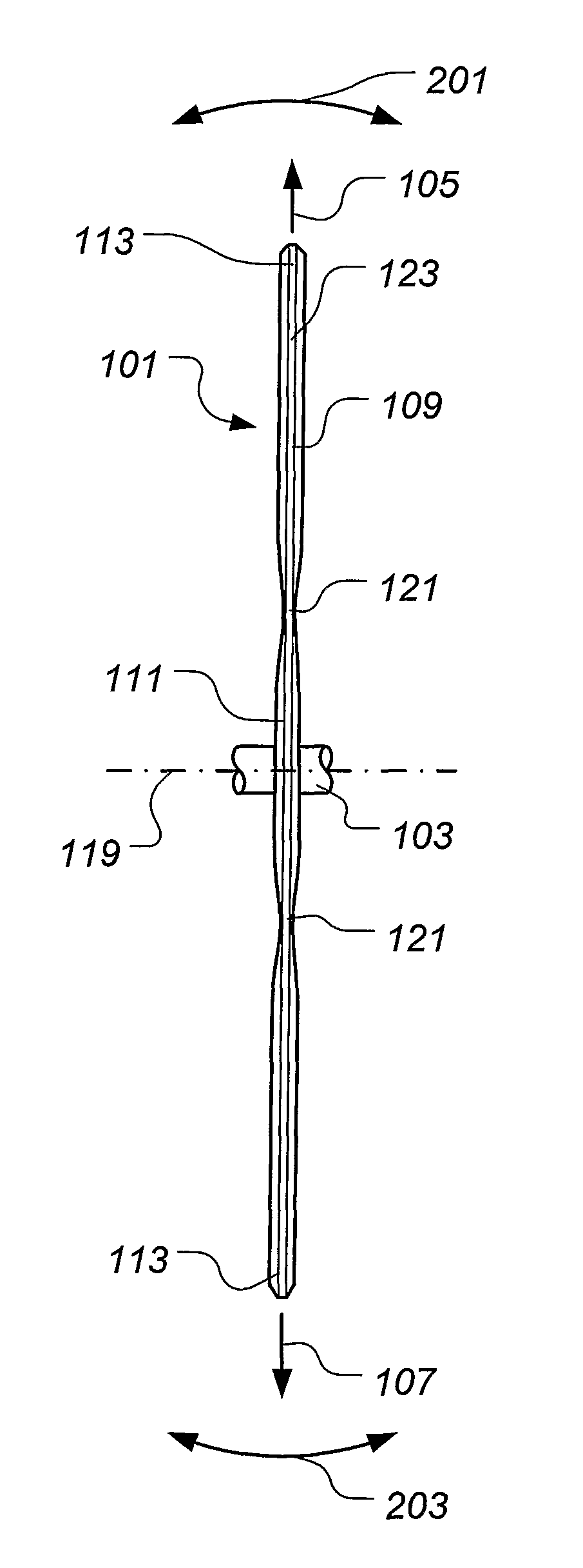
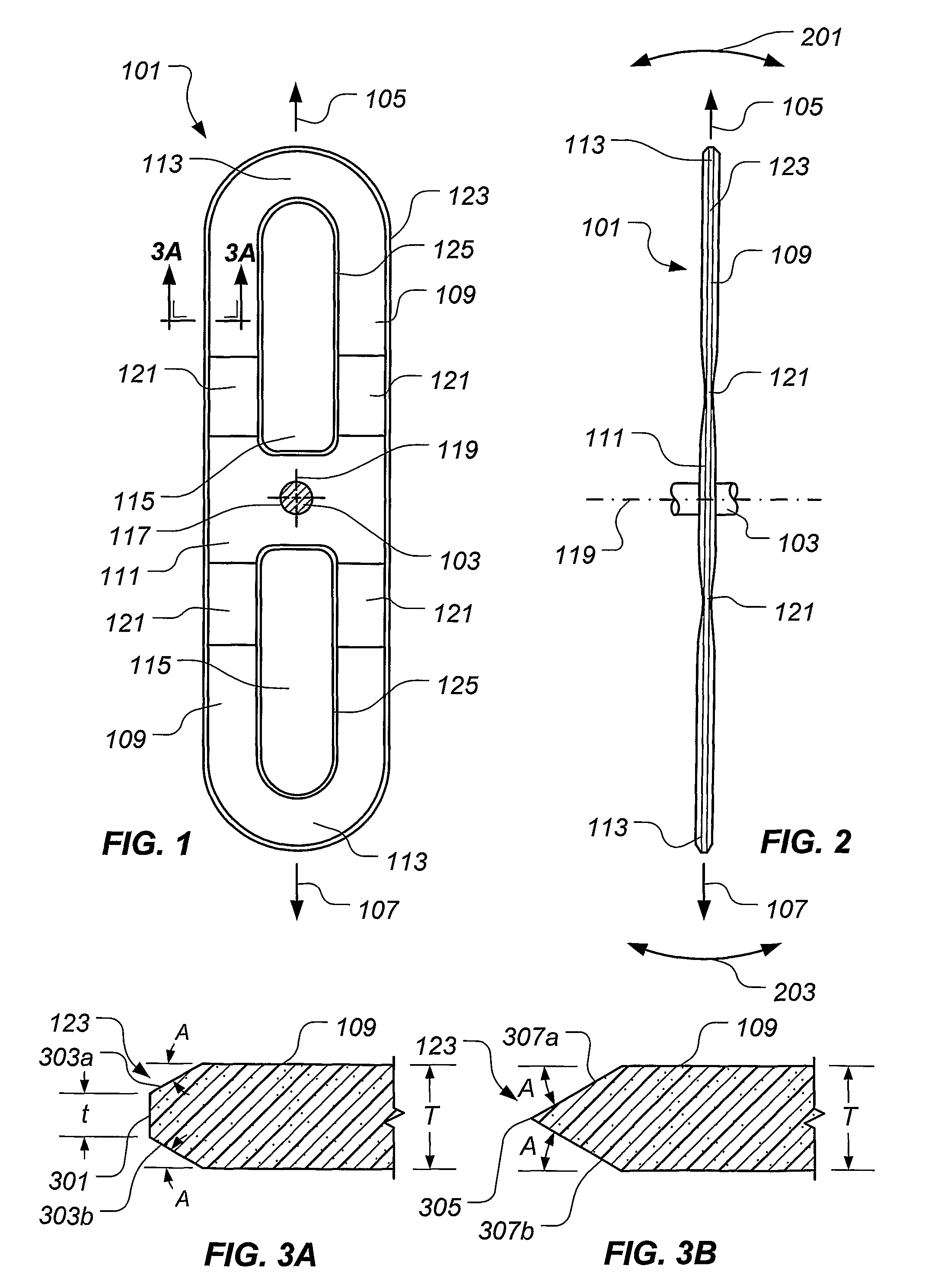
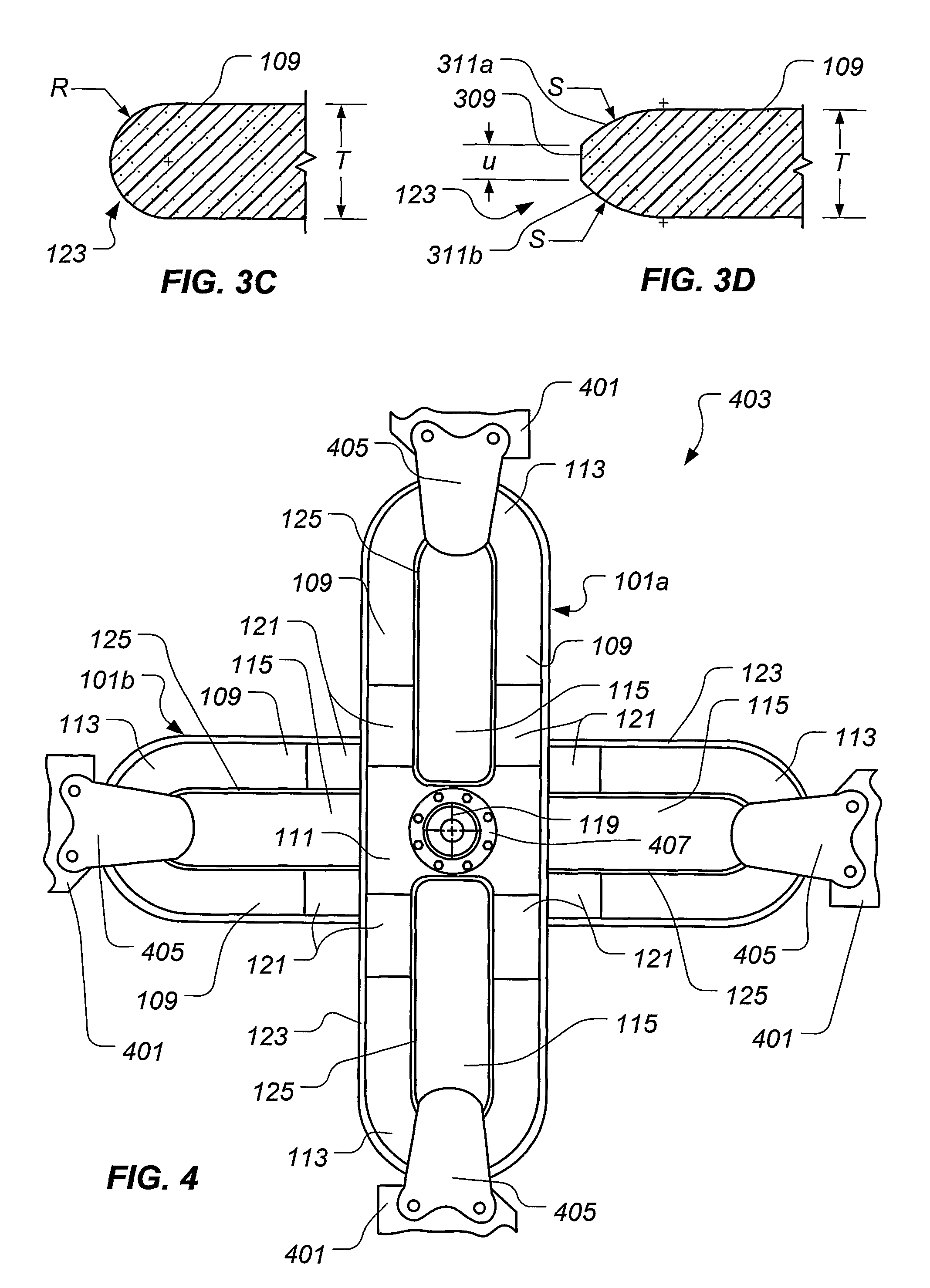
[0029]The present invention represents a helicopter rotor yoke exhibiting a tapered, chamfered, or otherwise reduced-thickness edge portion. Preferably, the reduced-thickness edge portion corresponds with an area of high interlaminar shear strain when the rotor yoke is in service....


PUM

PropertyMeasurementUnit
thicknessaaaaaaaaaa
thicknessesaaaaaaaaaa
degrees of freedomaaaaaaaaaa

Abstract

A rotor yoke includes a blade attachment portion, a mast attachment portion, and an intermediate portion extending between the blade attachment portion and the mast attachment portion. The intermediate portion, the blade attachment portion, and the mast attachment portion define an optional inner edge, such that the inner edge, if present, defines an opening. The rotor yoke further includes a peripheral, outer edge extending about the blade attachment portion, the intermediate portion, and the mast attachment portion. At least one of the outer edge and the inner edge, if present, includes a reduced thickness portion exhibiting a thickness that is less than a thickness of an adjacent portion of the rotor yoke.

Description

TECHNICAL FIELD[0001]The present invention relates to helicopters and, in particular, to yokes for coupling helicopter blades to a mast.DESCRIPTION OF THE PRIOR ART[0002]Each blade of the main rotor assembly of a helicopter must be connected to the main support mast, usually by means of a rotor yoke, in a manner allowing several degrees of freedom. Such an interconnection is subjected to high and repeated stresses of both torsional and centrifugal natures, and is therefore an extremely important component of the aircraft. Each blade must be able to rotate about its longitudinal axis to provide pitch control. Each blade must be able to flap in a direction perpendicular to the rotor plane to accommodate vertical loads. In some instances, each blade must be able to pivot within the rotor plane to provide for lead-lag control. The manner in which the blades are secured to the main support mast enables a helicopter to be controlled and maneuvered in flight.[0003]Various structures and me...

Claims


Application Information

Patent Timeline
Patent Type & Authority Patents(United States)
IPC IPC(8): F01D5/18
CPCB64C27/32B64C27/33Y10T29/49316
Inventor BASKIN, BRYAN K.
Owner TEXTRON INNOVATIONS
Why Eureka
Try Eureka