High capacity chiller compressor

a compressor and high-capacity technology, applied in the field of compressors, can solve the problems of large losses, large cooling applications such as industrial refrigeration systems or air conditioner systems that utilize pm motors, and are typically limited to capacities, so as to improve reliability, reduce maintenance requirements, and improve power output and efficiency

Active Publication Date: 2012-04-17
DAIKIN IND LTD
View PDF97 Cites 35 Cited by
  • Summary
  • Abstract
  • Description
  • Claims
  • Application Information

AI Technical Summary

Benefits of technology

[0022]The various embodiments of the invention include single stage and multi-stage centrifugal compressor assemblies designed for large cooling installations. The design enhances power output and efficiency, improves reliability and reduces maintenance requirements.
[0023]The variables in designing a high capacity chiller compressor include the diameter and length of the rotor and stator assemblies and the materials of construction. A design tradeoff exists with respect to the diameter of the rotor assembly. On the one hand, the rotor assembly has to have a large enough diameter to meet the torque requirement. On the other hand, the diameter should not be so great as to generate surface stresses that exceed typical material strengths when operating at high rotational speeds, which may exceed 11,000 rpm in certain embodiments of the invention, approaching 21,000 rpm in some instances. Also, larger diameters and lengths of the rotor assembly may produce aerodynamic drag forces (aka windage) proportional to the length and to the square of the diameter of the rotor assembly in operation, resulting in more losses. The larger diameters and lengths may also tend to increase the mass and the moment of inertia of the rotor assembly when standard materials of construction are used.
[0024]Reduction of stress and drag tends to promote the use of smaller diameter rotor assemblies. To produce higher power capacity within the confines of a smaller diameter rotor assembly, some embodiments of the invention utilize a permanent magnet (PM) motor. Permanent magnet motors are well suited for operation above 3600 rpm and exhibit the highest demonstrated efficiency over a broad speed and torque range of the compressor. PM motors typically produce more power per unit volume than do conventional induction motors and are well suited for use with VFDs. Additionally, the power factor of a PM motor is typically higher and the heat generation typically less than for induction motors of comparable power. Thus, the PM motor provides enhanced energy efficiency over induction motors.

Problems solved by technology

Also, larger diameters and lengths of the rotor assembly may produce aerodynamic drag forces (aka windage) proportional to the length and to the square of the diameter of the rotor assembly in operation, resulting in more losses.
Accordingly, large cooling applications such as industrial refrigeration systems or air conditioner systems that utilize PM motors are typically limited to capacities of 200 standard refrigeration tons (700 kW) or less.

Method used


Image

  • High capacity chiller compressor
  • High capacity chiller compressor
  • High capacity chiller compressor

Examples


Embodiment Construction

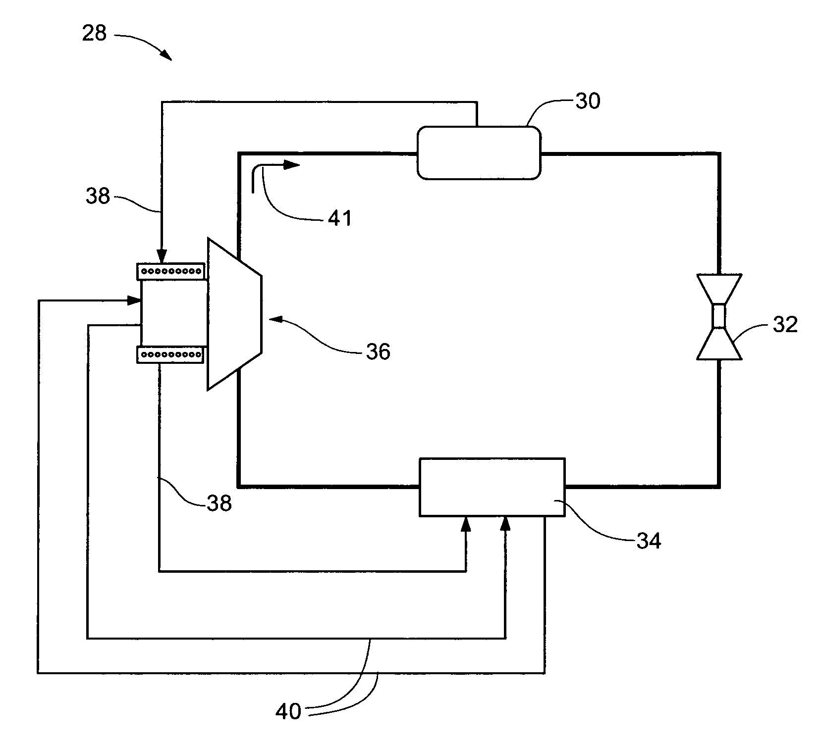
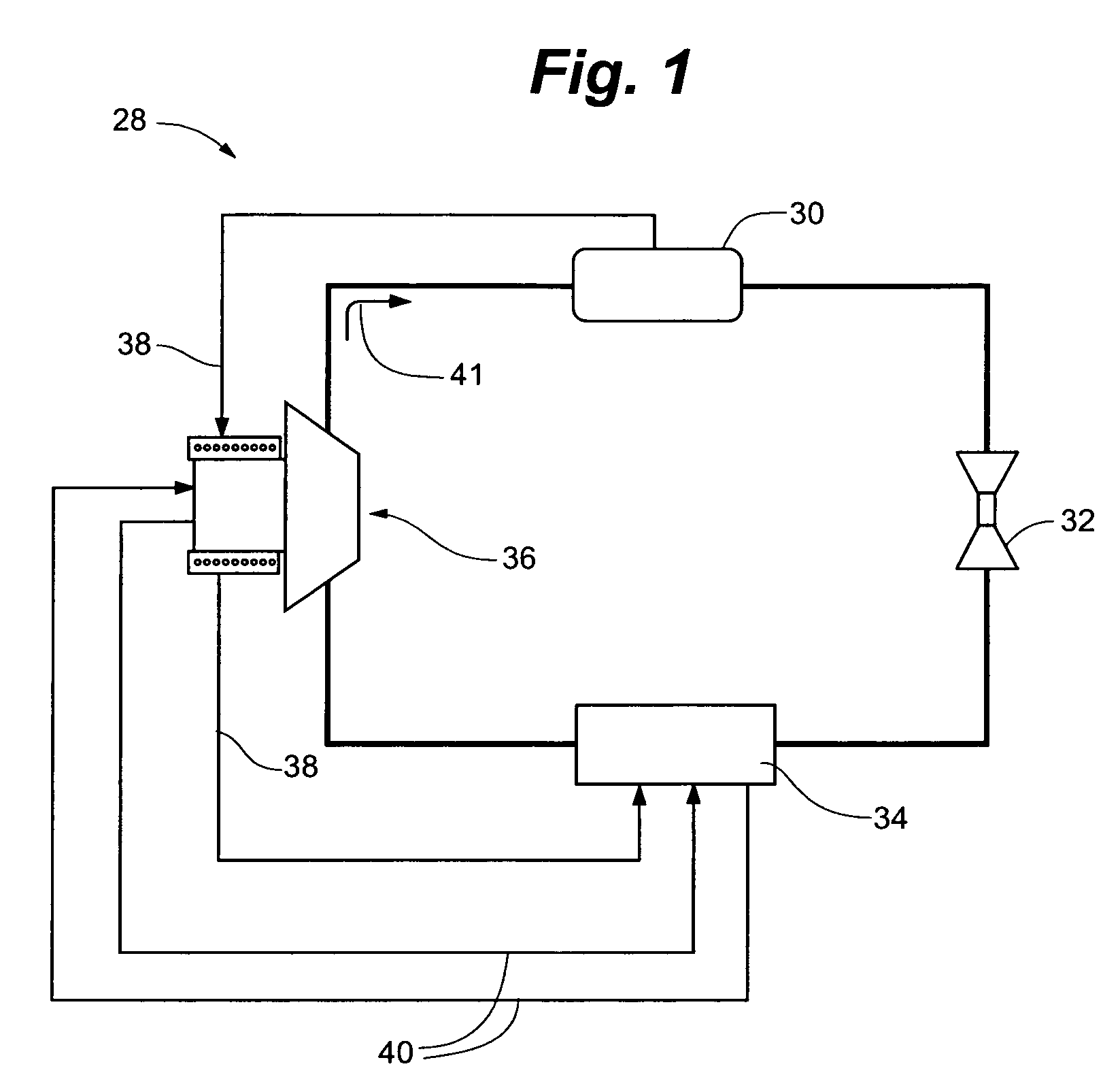
[0078]Referring to FIG. 1, a chiller system 28 having a condenser section 30, an expansion device 32, an evaporator section 34 and a centrifugal compressor assembly 36 is depicted in an embodiment of the invention. The chiller system 28 may be further characterized by a gas bypass circuit 38 and liquid bypass circuit 40 for cooling various components of the centrifugal compressor assembly 36.

[0079]In operation, refrigerant within the chiller system 28 is driven from the centrifugal compressor assembly 36 to the condenser section 30, as depicted by the directional arrow 41, setting up a clockwise flow as to FIG. 1. The centrifugal compressor assembly 36 causes a boost in the operating pressure of the condenser section 30, whereas the expansion device 32 causes a drop in the operating pressure of the evaporator section 34. Accordingly, a pressure difference exists during operation of the chiller system 28 wherein the operating pressure of the condenser section 30 may be higher than th...


PUM

PropertyMeasurementUnit
frequencyaaaaaaaaaa
frequencyaaaaaaaaaa
operating pressureaaaaaaaaaa

Abstract

A high efficiency, low maintenance single stage or multi-stage centrifugal compressor assembly for large cooling installations. The assembly is highly efficient by virtue of a variable frequency drive (VFD) that drives a permanent magnet motor and matches compressor speed with compressor load, a direct drive impeller that eliminates gearing losses, and magnetic bearings that reduce frictional losses. The back-emf produced by the motor provides an intermediate power source for the magnetic bearings in the event of a loss of electrical power. A cooling system provides direct cooling of the rotor with gas refrigerant, and cooling of the stator with liquid refrigerant. Modular construction allows the compressor to be retrofit with upgrades. An inlet guide vane system operates without need for oil lubrication. The use of light metal castings and elimination of gearing reduces the weight to one-third or less of comparably powered conventional units.

Description

RELATED APPLICATION[0001]This application claims the benefit of U.S. Provisional Application No. 60 / 849,865 filed Oct. 6, 2006, which is hereby fully incorporated by reference.FIELD OF THE INVENTION[0002]This invention relates generally to the field of compressors. More specifically, the invention is directed to large capacity compressors for refrigeration and air conditioning systems.BACKGROUND ART[0003]Large cooling installations, such as industrial refrigeration systems or air conditioner systems for office complexes, often involve the use of high cooling capacity systems of greater than 400 refrigeration tons (1400 kW). Delivery of this level of capacity typically requires the use of very large single stage or multi-stage compressor systems. Existing compressor systems are typically driven by induction type motors that may be of the hermetic, semi-hermetic, or open drive type. The drive motor may operate at power levels in excess of 250 kW and rotational speeds in the vicinity o...

Claims


Application Information

Patent Timeline
Patent Type & Authority Patents(United States)
IPC IPC(8): F25B31/00
CPCF04D25/0606F04D29/058F04D29/462F16C32/044F25B1/053F25B31/006F25B49/025H02K1/32H02K5/20H02K5/225H02K7/09H02K9/00F04D27/0261Y10T29/49826F25B2600/021H02K5/128H02K7/14H02K9/19H02K11/0047Y02B30/741F04D29/4213F05D2250/51H02K11/25F16C2360/44F04D29/5806H02K5/203Y02B30/70
Inventor DOTY, MARK C.CAMPAIGNE, JR., EARL A.WATSON, THOMAS E.BUTLER, PAUL K.CLINE, QUENTIN E.SHOWALTER, SAMUEL J.
Owner DAIKIN IND LTD
Why Eureka
Try Eureka