Rapid acquisition, pointing and tracking optical system for free space optical communications

a free space optical communication and optical system technology, applied in the field of optical tracking, can solve the problems of low production cost, lack of speed, precision, reliability, and unwieldiness of high-speed laser target tracking, and achieve the effect of low production cost and small size and weigh

a free space optical communication and optical system technology, applied in the field of optical tracking, can solve the problems of low production cost, lack of speed, precision, reliability, and unwieldiness of high-speed laser target tracking, and achieve the effect of low production cost and small size and weigh

US8160452B1Active Publication Date: 2012-04-17SPACE PHOTONICS

Image

  • Rapid acquisition, pointing and tracking optical system for free space optical communications
  • Rapid acquisition, pointing and tracking optical system for free space optical communications
  • Rapid acquisition, pointing and tracking optical system for free space optical communications

Examples


Embodiment Construction

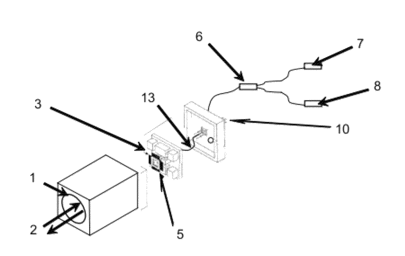
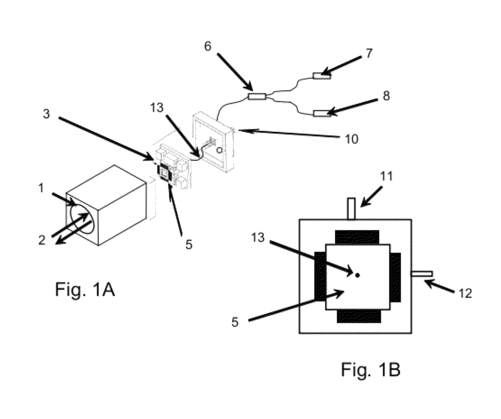
[0025]With reference to FIGS. 1A and 1B, the preferred embodiment of the present invention may now be described. The preferred embodiment is a laser communications transceiver incorporating the rapid acquisition, tracking and pointing system described herein, but the invention is not so limited, and in fact may be put to many other logical applications as will be apparent to those skilled in the art. The preferred embodiment includes an optical system consisting of beam expansion optics and focusing optical design that provides the reciprocal direction reflection of an incoming beam as described herein.

[0026]Now turning to a description of the particular elements of the preferred embodiment of the present invention, as shown in FIGS. 1A and 1B, the device incorporates an optical fiber 13, as are well known in the art. Any other means by which light may be transmitted along a path could be employed in alternative embodiments in place of optical fiber 13. The purpose of optical fiber ...


PUM


Abstract

An acquisition, pointing and tracking system for free space optical communications systems performs the pointing and tracking function internally by way of translating an internal optical fiber in the focal plane of the transceiver telescope with a reflecting mirror in the telescope focal plane of each linked transceiver. The beam reflected from the mirror records the exact direction of the reflected beam at the transmitting beam's transceiver terminal, providing the transmitting source to lock on to the receiving telescope, allowing for the link to be acquired.

Description

STATEMENT REGARDING FEDERALLY SPONSORED RESEARCH OR DEVELOPMENT[0001]The U.S. Government has a paid-up license in this invention and the right in limited circumstances to require the patent owner to license others on reasonable terms as provided for by the terms of contract no. F29601-02-C-0021 awarded by the United States Air Force Research Laboratory.BACKGROUND OF THE INVENTION[0002]The present invention relates to the field of optical tracking, and in particular to the field of laser target acquisition and tracking. More particularly, in various embodiments the present invention relates to a beam pointing and tracking apparatus and method for laser target acquisition and tracking using translational stages that move an optical fiber in the focal plane of the transmitting and receiving optical system while surrounded by a reflecting mirror in the focal plane that also moves in conjunction with the optical fiber.[0003]Laser targeting and tracking systems are today employed in a vas...

Claims


Application Information

Patent Timeline
17 Apr 2012
Publication
US8160452B1
IPC
H04B10/00
CPC
H04B10/118
Inventors
TIDWELL, TERRY L.; GREGORY, JEFFREY T.