
Electrowinning apparatus and process

a technology of electrolysis apparatus and process, applied in the field of electrolysis, can solve the problems of low efficiency of processing dilute metal source, high capital cost, and electrode fouling, and achieve the effects of low efficiency when processing dilute metal sources, low capital cost, and high capital cos

Inactive Publication Date: 2012-06-19
ELTRON RES
View PDF33 Cites 9 Cited by
  • Summary
  • Abstract
  • Description
  • Claims
  • Application Information

AI Technical Summary

Benefits of technology

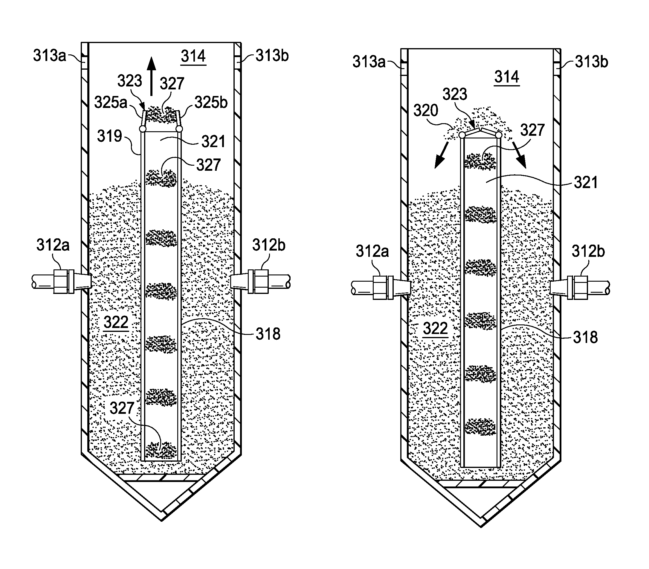
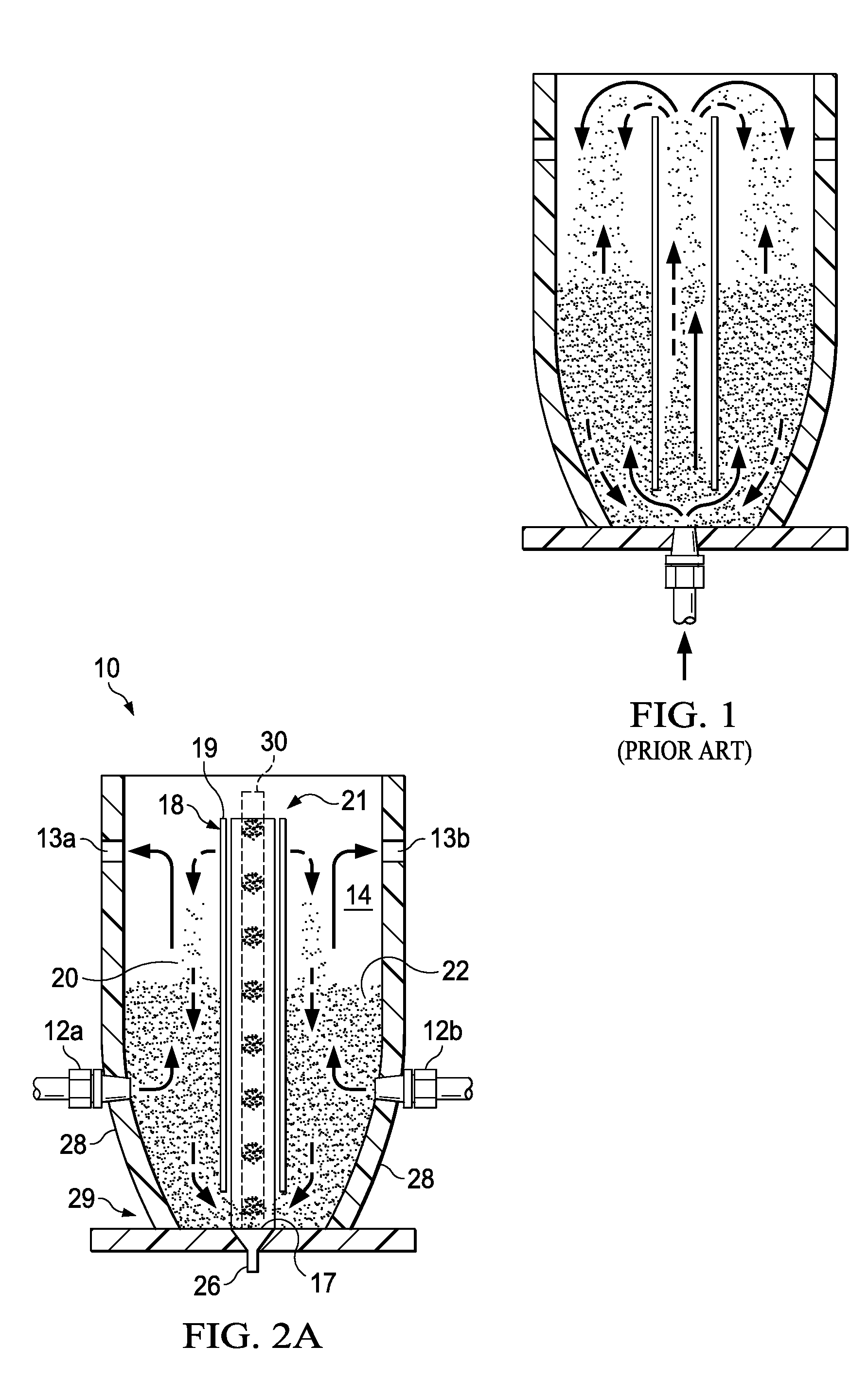
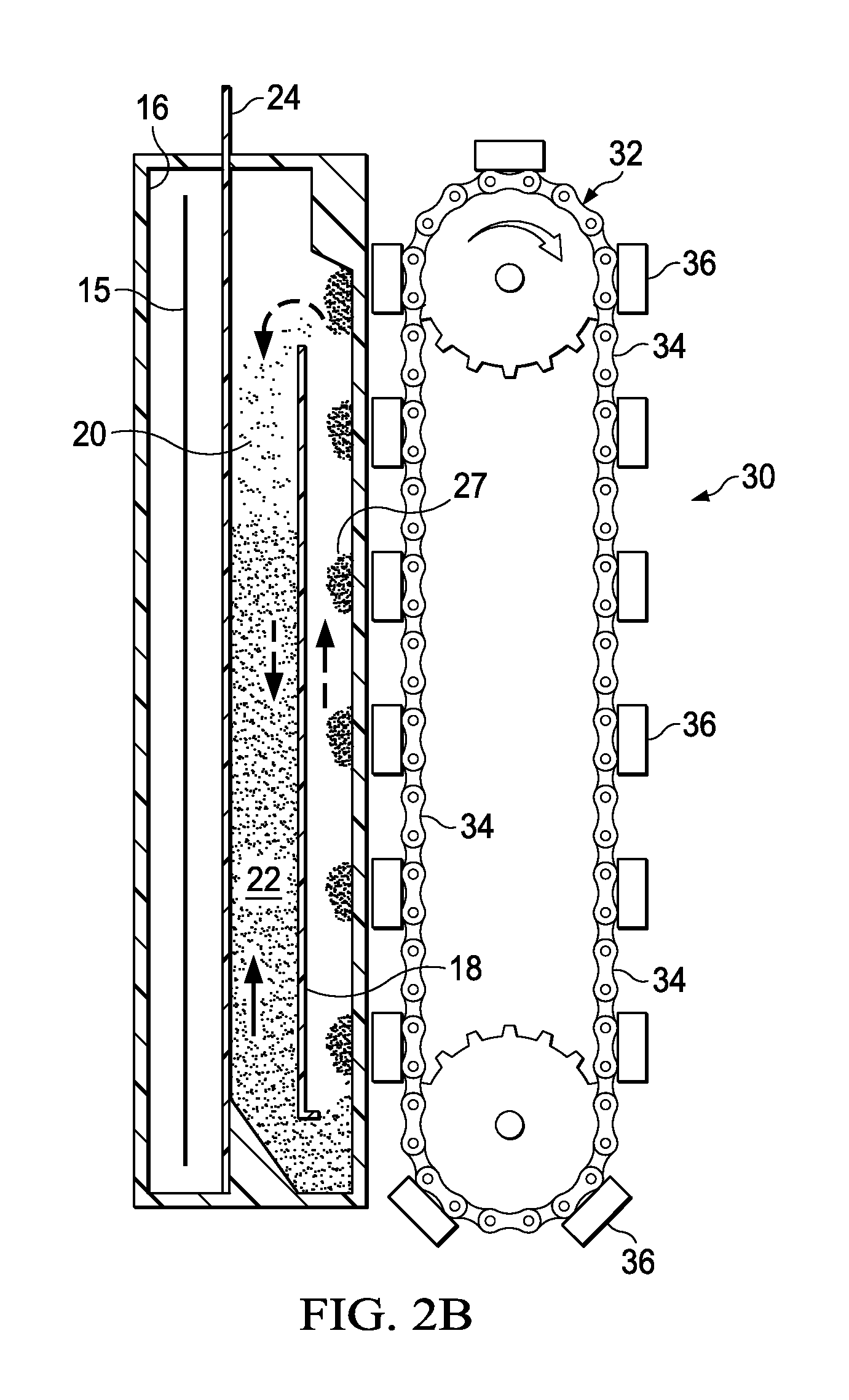
"The invention provides a spouted bed reactor for electrowinning heavy metals from a fluid stream, which includes a particle bed and a particle bed churning device for spouting particles independently of the fluid stream. The reactor can be used in a system with an ion-permeable membrane separating the anolyte and catholyte chambers. The cathode particles can be magnetic and the particle bed churning device can comprise a magnetic conveyor assembly or an array of electromagnets. The system also includes an electrowinning process for reducing heavy metals using a catholyte solution containing at least one heavy metal salt dissolved therein. The spouting of the cathode particles is independent of the flow of the catholyte solution, which allows for the particles to be redistributed or chum the particle bed without needing to be carried by the flow of the catholyte solution. The invention addresses shortcomings associated with prior devices or methods and provides a more efficient and effective process for electrowinning heavy metals."

Problems solved by technology

These advantages are in many cases offset by common drawbacks such as medium to high capital cost, possible side reactions, and electrode fouling, corrosion, or other undesirable chemical reaction.
Many existing systems suffer from awkward product removal, in some cases requiring equipment disassembly.
Another common drawback of existing electrowinning technologies is low efficiency when processing dilute sources of metals.
Most existing methods cannot be satisfactorily scaled up for processing large volumes of liquid and increased space velocities.
These electrolytic systems are typically either planar or annular in design and operate at only moderate current densities, thus requiring large electrodes with correspondingly larger capital investments.
Additionally, such cells generally suffer from large Ohmic losses due to significant interelectrode distances.
Conventional plate and frame electrolytic technologies are not suitable for recovery of metals from dilute streams containing less than 1000 ppm metal.
Packed beds tend to become occluded by metal deposition, however, and are subject to shorting by interelectrode dendritic growth.
Fluidized bed electrolytic systems still suffer from energy-intensive fluidization and dendrite growth leading to bed coagulation and process instability.
Although SET has been studied for many years, it has until recently been hampered by scale-up issues due to the typically annular design and unsuitability at metal concentrations below a few thousand parts per million.
The linking or coupling of cathode spouting to electrolyte motion imposes certain inherent limitations on the technology.
For instance, since a high flow rate is typically required to achieve spouting, operation parameter flexibility is limited.
For heavy materials, such as plated metals, this can waste large amounts of energy to jet the electrolytic fluid fast enough to cause spouting.
Also, most electrolyte passes through the spout and bypasses the bed so that excessive amounts of fluid transport occur and most fluid is simply recirculated without being treated.
In many cases the result is low per pass removal rates, necessitating batch mode operation and increasing energy demands for pumping.
Since most industrial metal recovery applications are more conducive to flow-through treatment, batch mode operation can be especially disadvantageous.
At metal concentrations of less than about 2000 ppm, the inherent problems of jetted SET are often glaringly apparent.

Method used


Image

  • Electrowinning apparatus and process
  • Electrowinning apparatus and process
  • Electrowinning apparatus and process

Examples


example 1

Nickel, Copper Removal

[0135]For a given set of MSET operating conditions, the relative electrowinning efficiency for each metal closely follows the relative reduction potentials making it possible for selective electro-refining from mixed sources. The effect of pH also has an influence on electrowinning efficiency and final metal concentration of the effluent in addition to the feed flow rate and current density as mentioned above. These effects are illustrated in FIG. 11 for nickel using a MSET system configuration similar to that shown in FIGS. 4A-B with different feed solution flow rates and pH (constant current density). At high feed-flow rate there is no removal of nickel, however, these same conditions promote the good copper removal shown in FIG. 12. Reducing the feed flow rate or raising the pH leads to nickel removal, even at very low concentrations. Higher current densities will further increase nickel (and zinc) removal rates. The performance improvement of a MSET system ...

example 2

Parameterization of Process Variables

[0137]The new magnetically spouted electrolytic technology has made possible for the first time the parameterization of the process variables, allowing significant advances to be made in electrowinning rate, efficiency and selectivity. These advances have provided the performance necessary to design simple, low-cost, flow-through metal recovery and refining systems for direct capture of valuable metals from a variety of aqueous sources too dilute to be economically viable with currently available technology.

[0138]Since the metal removal rate in a flow-through treatment system is paramount, a series of experiments were conducted to determine how to best increase metal removal rates by adjusting the flow rate and cell current density. The range of operating conditions examined is given in Table 2 and Table 3. The range of flow rates encompassed an acceptable range for a pilot-scale system, such as that described above and illustrated in FIGS. 6 and...

example 3

Metal Oxide Production

[0149]During the course of carrying out the foregoing studies it was discovered that when the anode and cathode solutions were isolated from one another, a partial electrical short from the system was eliminated, and greatly reduced the current density (at constant voltage) at the cathode by about 10 times. This was found to be important for scale-up reactor process design, since the partial electrical short had not been previously identified and its contribution to the current density would change with changing reactor size and with the number of reactors in series. The greatly reduced current density allowed for a new process / production capability of this technology to be discovered, i.e., the selective production of reduced metal oxides by partial reduction of target metals in the presence of dissolved oxygen. This has not been previously described with respect to spouted cathode reactor technologies. Two of the metal oxides the system produced directly from...


PUM

PropertyMeasurementUnit
angleaaaaaaaaaa
angleaaaaaaaaaa
mean diameteraaaaaaaaaa

Abstract

Apparatus and processes are disclosed for electrowinning metal from a fluid stream. A representative apparatus comprises at least one spouted bed reactor wherein each said reactor includes an anolyte chamber comprising an anode and configured for containing an anolyte, a catholyte chamber comprising a current collector and configured for containing a particulate cathode bed and a flowing stream of an electrically conductive metal-containing fluid, and a membrane separating said anolyte chamber and said catholyte chamber, an inlet for an electrically conductive metal-containing fluid stream; and a particle bed churning device configured for spouting particle bed particles in the catholyte chamber independently of the flow of said metal-containing fluid stream. In operation, reduced heavy metals or their oxides are recovered from the cathode particles.

Description

STATEMENT REGARDING FEDERALLY SPONSORED RESEARCH OR DEVELOPMENT[0001]The U.S. Government has a paid-up license in this invention and the right in limited circumstances to require the patent owner to license others on reasonable terms as provided for by the terms of Grant No. EP-D-04-022 awarded by the U.S. Environmental Protection Agency and Grant No. DE-FG02-05ER84320 awarded by the U.S. Department of Energy.CROSS-REFERENCE TO RELATED APPLICATIONS[0002]Not applicable.BACKGROUND[0003]1. Technical Field[0004]The present invention generally relates to the field of electrowinning, also referred to as electrorefining or electroextraction, and more specifically to apparatus and processes for electrolytically removing metals from conductive liquids and facilitating recovery of such metals. Still more specifically, the invention relates to such apparatus and processes which provide for particulate cathode bed churning that is uncoupled to the flow of catholyte.[0005]2. Description of Relat...

Claims


Application Information

Patent Timeline
Patent Type & Authority Patents(United States)
IPC IPC(8): C25C7/00C25C1/20C25C1/10C25C1/08C25C1/06C25C1/02C25C1/00C25C1/12C25C7/02C25C1/22C25C1/18C25C1/16C25C1/14
CPCC25C1/12C25C1/22C25C7/002
Inventor BUSCHMANN, WAYNE E.
Owner ELTRON RES
Learn More