Electrostatic comb-drive micromechanical actuator

a micromechanical actuator and comb-drive technology, applied in the direction of electrostatic generator/motor, optics, instruments, etc., can solve the problems of high metallic mass, less suitable for mass production, and high cost of hybrid-mounted systems, so as to achieve the effect of simple hermetically sealed wafer level packaging, increased length and suitably increased torqu

Active Publication Date: 2012-07-03
FRAUNHOFER GESELLSCHAFT ZUR FOERDERUNG DER ANGEWANDTEN FORSCHUNG EV
View PDF8 Cites 1 Cited by
  • Summary
  • Abstract
  • Description
  • Claims
  • Application Information

AI Technical Summary

Benefits of technology

[0031]With implementation of the actuator element as a micro-mirror a dual-axis micro-mirror scanner can in this manner be achieved, which can attain the large scanning angle necessary for high resolution laser projection in non-resonant operation of the slow scanning axis, without the scanner itself at the same time becoming too fragile i.e. the slow axis can be implemented with a resonant frequency of around 1 kHz or higher. Here the slow axis corresponds to the tilting movement about the outer tilting axis. Horizontal deflections are enabled via the inner tilting axis in resonant operation with the necessary high frequency. With electrostatic drives on both axes a micro-mirror scanner of this kind can be produced wholly from silicon, and silicon dioxide for the insulation, apart from the mirror coating layer and connector panels. In turn this enables comparatively simple hermetically sealed wafer level packaging based on standard wafer bonding technology.
[0032]A micromechanical actuator of this kind, for example in the form of the dual-axis micro-mirror scanner as described, can also be implemented in a very compact form. In an embodiment of such a compact implementation the first and second comb-type or finger-type electrodes are designed on both sides of the outer tilting axis, wherein the electrode fingers are in each case aligned parallel to the outer tilting axis. This enables the arrangement of the comb-type or finger-type electrodes both for the outer tilt drive, and also for the inner tilt drive, on the same two opposing sides of the actuator, i.e. of the outer tilting axis, so that while the actuator increases in length it does not, however, increase in width. Via the increase in length the torque can be suitably increased by increasing the number of the comb-type or finger-type electrodes, without at the same time altering the width of the actuator. In this manner it is possible to integrate such an actuator into flat items of equipment, such as, for example, flat mobile phones.

Problems solved by technology

In addition to the already significant disadvantage of the layer stresses, or layer stress gradients, which are very difficult to avoid with metal deposition and can result in severe distortion of the actuator, and the high metallic mass that the actuator must carry with it, an even greater problem arises relating to any attempt to encapsulate such an actuator using wafer bonding techniques at wafer level.
In most cases the thermal mismatches of the materials involved rule out the use of a wafer level packaging method on account of the high temperatures.
Further significant disadvantages of the electromagnetic drives ensue from the necessity of generating, in addition to moving planar coils, an external magnetic field by means of hybrid applied permanent magnets positioned as densely as possible on the micro-actuator.
Such a hybrid-mounted system is more expensive and less suitable for mass production than an electrostatic actuator.
In order still to be able to achieve sufficiently large scanning amplitudes with what remains a very high scanning frequency, horizontal scanners are usually operated in resonance, which results in a sinusoidal velocity characteristic and thus an undesirable, non-homogeneous distribution of light intensity in the line direction.
However, these have the disadvantages noted above.
At this point in time micromechanical actuators of known art with non-resonant electrostatic drives are unable to achieve such torques with the required size of micro-mirror and high deflections.
However, as a result of the short lever arm the torque that can be achieved is also very much lower than with a comparable arrangement of electrodes far from the axis with a large lever arm.
While the mirror diameter and resonant frequency in this micro-mirror scanner fulfil the above requirements, the mechanical quasi-static tilt angle obtained of + / −4.2° does not satisfy the specifications for high resolution projection.
This is only one example of many that show that up to the present time a standard design of a dual-axis micro-mirror scanner with electrodes positioned close to the axis is not suitable for achievement of the large scanning angles of more than + / −7° required for the slow quasi-static axis, if at the same time the mirror diameter is not to fall below a minimum of 1 mm, and the resonant frequency of the slow axis is not to be significantly less than 1 kHz.
However, new problems would arise in these circumstances, since the moving mass thereby increases significantly, the sensitivity to accelerations increases and the space requirement is then not only very large along the fast mirror axis, but also at right angles to it.
This is undesirable for the applications that are presently being pursued, however, since accurate guidance via the tilting axes is not possible.
As a result of this construction both chip edge lengths are approximately the same size and are thus unsuitable for installation in flat items of equipment, in particular, flat mobile phones.
This likewise does not fulfil the above requirements for a high-resolution laser display.

Method used


Image

  • Electrostatic comb-drive micromechanical actuator
  • Electrostatic comb-drive micromechanical actuator
  • Electrostatic comb-drive micromechanical actuator

Examples


Embodiment Construction

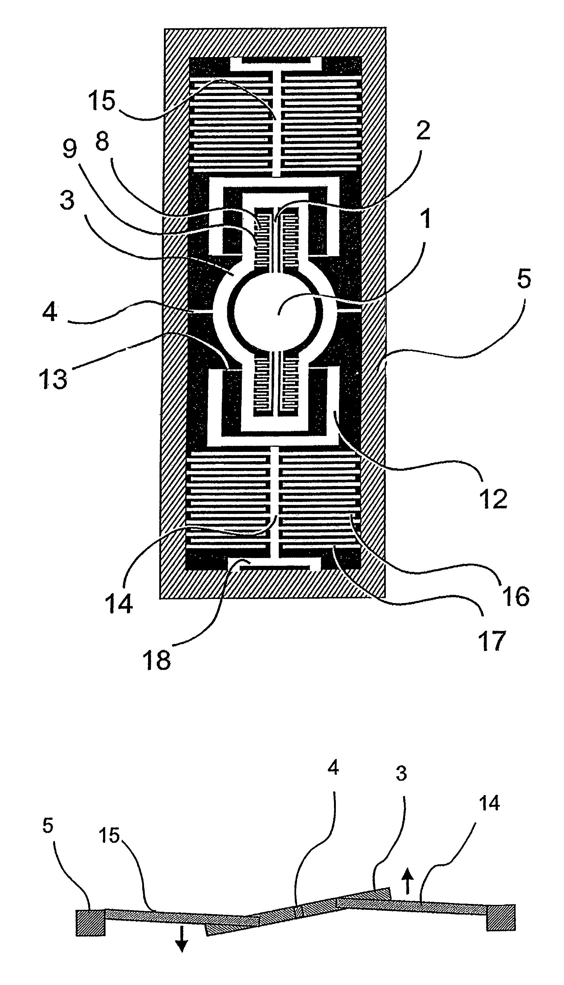
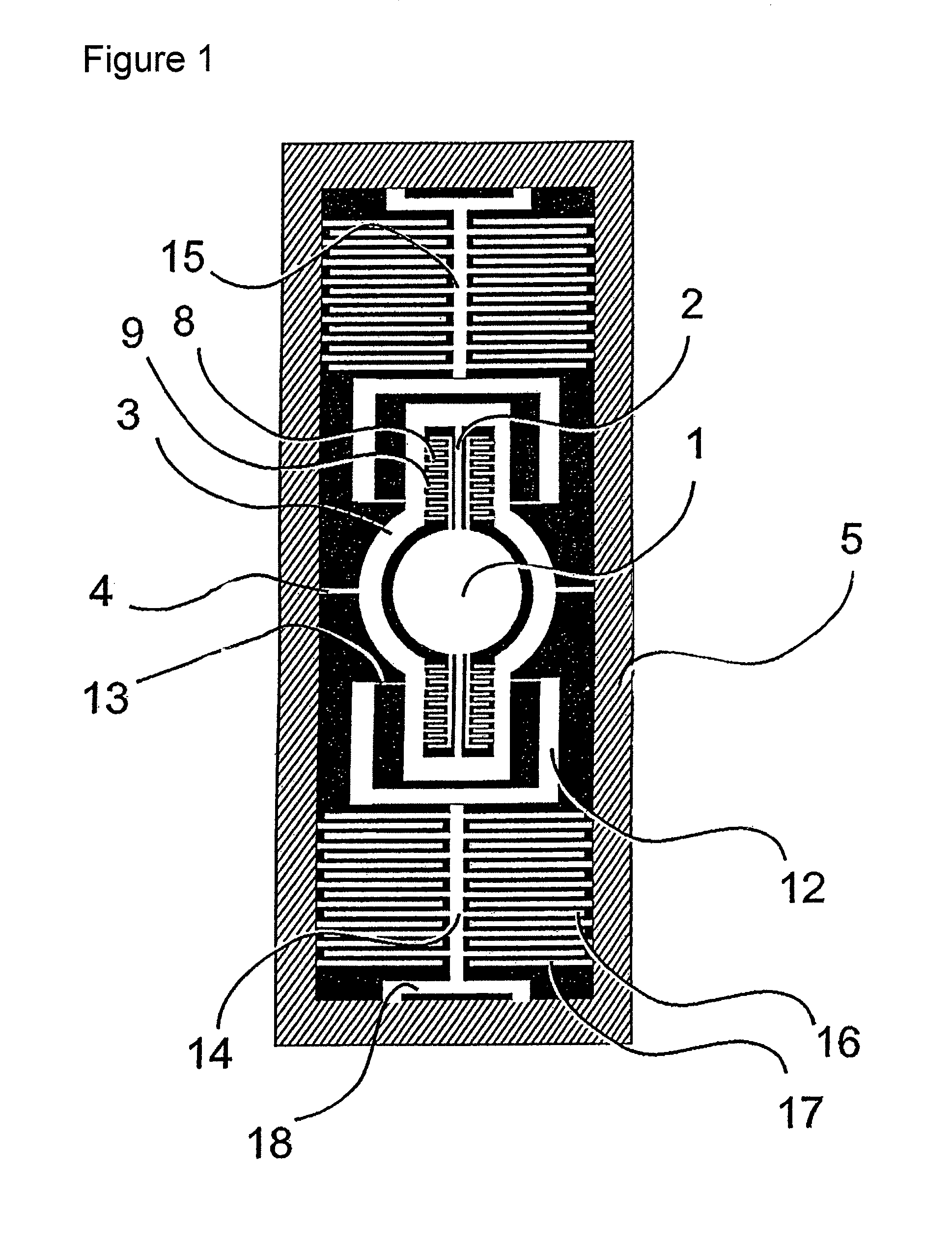
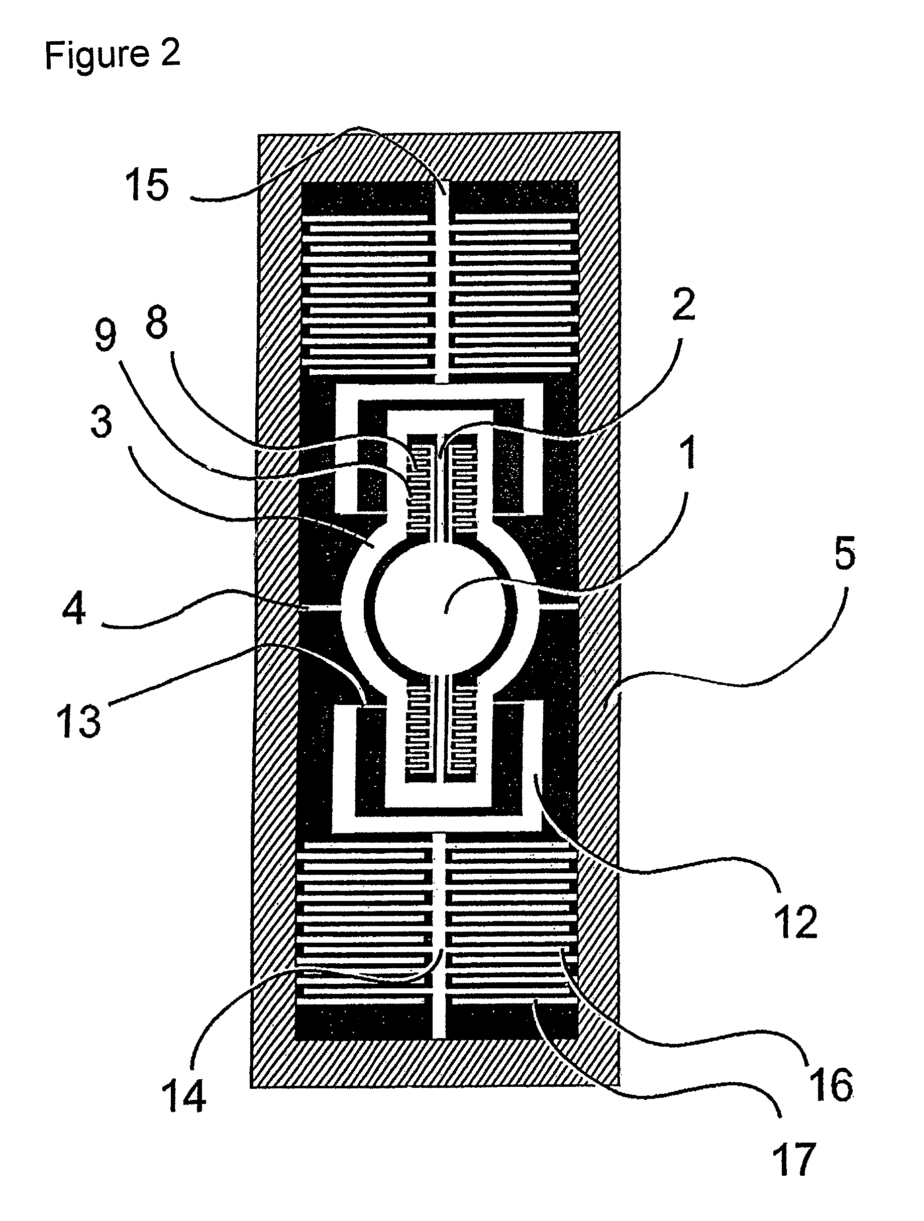
[0039]In what follows configurations for dual-axis micro-mirror scanners according to the present invention are elucidated; these have a mirror diameter of at least 1 mm and a slow axis resonant frequency of around 1 kHz or higher, and enable a mechanical deflection angle for the slow axis of around + / −7° or more. Here FIGS. 1 and 2 show configurations of such a micro-mirror scanner, in which at the same time, a small chip edge length is achieved in the dimension parallel to the mirror surface.

[0040]The configuration of FIG. 1 shows a micro-mirror 1 that is suspended via torsion springs 2 about a tilting axis running along the torsion springs 2 (inner tilting axis) such that it can rotate in a moving frame (gimbal) 3 surrounding it. The micro-mirror 1 can be tilted about the inner tilting axis in the moving frame 3, by means of two electrostatic tilt drives that have vertically offset comb electrodes 8, 9. The moving frame 3 (inner frame) is in turn suspended via torsion springs 4 a...


PUM


Abstract

The invention relates to a micromechanical actuator, especially a micro-mirror scanner, comprising an actuator unit in an outer frame which unit is suspended in the outer frame via two torsion elements, and electrostatic tilt drives from intermeshing first and second comb-type electrodes which are off-set from each other vertically. The first electrodes are rigidly connected to the outer frame and the second electrodes to the outer frame via an outer connecting element and to the actuator unit via an inner connecting element. The inner connecting element has a spring which extends in parallel to the outer tilting axis, which is connected to the same in a section of the actuator unit close the outer tilting axis, and which is designed and arranged to be rigid in the vertical direction and flexible at a right angle to the vertical direction. The micromechanical actuator according to the invention allows the use in a micro-mirror scanner whose slow axis is non-resonantly driven with excursions of >+ / −7°, lateral mirror sizes having dimensions of 1 mm and more and a resonant frequency of >1 kHz and can be integrated even into flat mobile phones.

Description

CROSS REFERENCE TO RELATED APPLICATION[0001]The present application is a U.S. National Stage of International Application No. PCT / EP2009 / 008160, filed Nov. 17, 2009, designating the United States and claiming priority to German application DE 10 2008 059 634.5, filed Nov. 28, 2008.TECHNICAL FIELD OF APPLICATION[0002]The invention relates to a micromechanical actuator, in particular a micro-mirror scanner, comprising an actuator unit in an outer frame, which unit is suspended in the outer frame via two torsion elements, extending along an outer tilting axis of the actuator unit, and an electrostatic tilt drive of intermeshing first and second comb-type electrodes, of which the first electrode is rigidly connected with the outer frame and the second electrode is in each case connected with the actuator unit.BACKGROUND OF THE INVENTION[0003]For purposes of driving micromechanical silicon actuators (MEMS actuators) electrostatic forces have been successfully deployed for several decades...

Claims


Application Information

Patent Timeline
Patent Type & Authority Patents(United States)
IPC IPC(8): G02B26/08
CPCG02B26/0841
Inventor HOFMANN, ULRICHOLDSEN, MARTENWAGNER, BERND
Owner FRAUNHOFER GESELLSCHAFT ZUR FOERDERUNG DER ANGEWANDTEN FORSCHUNG EV
Why Eureka
Try Eureka