Optical article and method for producing the same

a technology of optical articles and optical sheets, applied in the field of optical articles, can solve the problems of film separation, poor adhesion of gold, and concern for the durability of the antireflection layer that includes the ito layer, and achieve the effects of low resistance, excellent compatibility, and low sheet resistan

Active Publication Date: 2012-07-10
HOYA LENS MFG PHILIPPINES
View PDF13 Cites 11 Cited by
  • Summary
  • Abstract
  • Description
  • Claims
  • Application Information

AI Technical Summary

Benefits of technology

[0009]One aspect of the invention provides a method for producing an optical article (optical element), comprising forming a light-transmissive first layer on an optical substrate directly or with an additional layer in between, and forming a silicide material, light-transmissive thin film on the surface of the first layer. The silicide is a transition metal silicide, which has low resistance, exhibits excellent compatibility with silicon-based compounds and / or oxides, such as silicon oxide and organosilicon compounds, and is almost stable to acids other than fluoric acid. Accordingly, an optical article having low sheet resistance and high durability can be produced. Therefore, an optical article having an antistatic function and / or an electromagnetic wave shielding function, for example, can be produced and provided more easily. Low resistance as used herein means lower electrical resistance.
[0010]Silicides have low resistance. For example, the resistivity of TiSi2, a kind of titanium silicide, is 2×10⁻⁵ Ω·cm, whereas the resistivity of ITO is 10−3 to 10−4 Ω·cm. Thus the resistivity of a silicide is less than the resistivity of ITO. Accordingly, by employing a silicide layer as an electrically conductive layer, even in the case of a thin film, the layer resistance on the substrate can be sufficiently reduced. Therefore, the light transmittance of the silicide film can be secured, and the thin film of silicide can be inserted without change or with little change from the existing antireflection layer structure.
[0012]Typically, the first layer is included in an inorganic or organic antireflection layer that is laminated on the optical substrate with a hard coating layer in between, or with a primer layer and a hard coating layer in between. Forming the first layer includes forming one first layer or a plurality of first layers of an antireflection layer having a multilayer structure. The sheet resistance of the multilayer antireflection layer can thereby be reduced. The first layer may alternatively be the inorganic or organic antireflection layer. The method may further include forming an antifouling layer on the first layer directly or with an additional layer in between.
[0013]Another aspect of the invention provides an optical article comprising an optical substrate, a light-transmissive first layer formed on the optical substrate directly or with an additional layer in between, and a silicide material, light-transmissive thin film formed on the surface of the first layer. The sheet resistance of the layer and a system of films or layers, including the above-referenced layer, formed on the optical substrate can be reduced by forming the silicide material, light-transmissive thin film on the surface of the first layer. Accordingly, electrical conductivity can be imparted to the films or layers formed on the surface of the substrate, thereby imparting an antistatic function, an electromagnetic shielding function, and the like, or providing such functions. Further, as compared with ITO, silicides have higher stability against acid, alkali, and like chemicals, and therefore, a reduction in durability can be suppressed. This can thus be applied to personal articles (elements, products) for which antistatic performance is required, such as spectacle lenses, camera lenses, PDA displays, DVDs, and other optical articles.
[0016]Still another aspect of the invention provides a system that includes the above optical article with one side thereof facing the outside, and is used for seeing an image through the optical article. A typical example of such a system is an information-processing apparatus including a clock, a display, a terminal with a display, etc. Buildup of static electricity on the display surface can be prevented, and also the electromagnetic shielding ability can be improved.

Problems solved by technology

Therefore, when such a layer is employed on a spectacle lens, because human sweat is salty and acidic, the durability of the antireflection layer that includes the ITO layer may be of concern.
However, an antireflection layer, a hard coating layer, an antifouling layer, and like layers formed on the surface of the substrate of an optical article often primarily consist of a silicon-based compound or oxide, so the compatibility with such a layer is of concern.
For example, gold generally has poor adhesion, and film separation may thus occur.
Silicides have low resistance.

Method used


Image

  • Optical article and method for producing the same
  • Optical article and method for producing the same
  • Optical article and method for producing the same

Examples


example 1

2.1 Example 1

Sample S1

2.1.1 Selection of Lens Substrate and Formation of Hard Coating Layer

[0056]A coating liquid for forming a hard coating layer 2 was prepared as follows. First, 4.46 parts by weight of acid anhydride curing agent (trade name: liquid curing agent (C2) (manufactured by Arakawa Chemical Industries)) was mixed with 20 parts by weight of epoxy resin / silica hybrid (trade name: Compoceran E102 (manufactured by Arakawa Chemical Industries)), and stirred to give a coating liquid. The obtained coating liquid was applied onto a substrate 1 using a spin coater to a predetermined thickness, thereby forming a hard coating layer 2.

[0057]As the substrate 1, a plastic lens substrate for spectacles having a refractive index of 1.67 (manufactured by SEIKO EPSON, trade name: Seiko Super Sovereign (SSV)) was used. The coated lens substrate was calcined at 125° C. for 2 hours.

2.1.2 Formation of Antireflection Layer

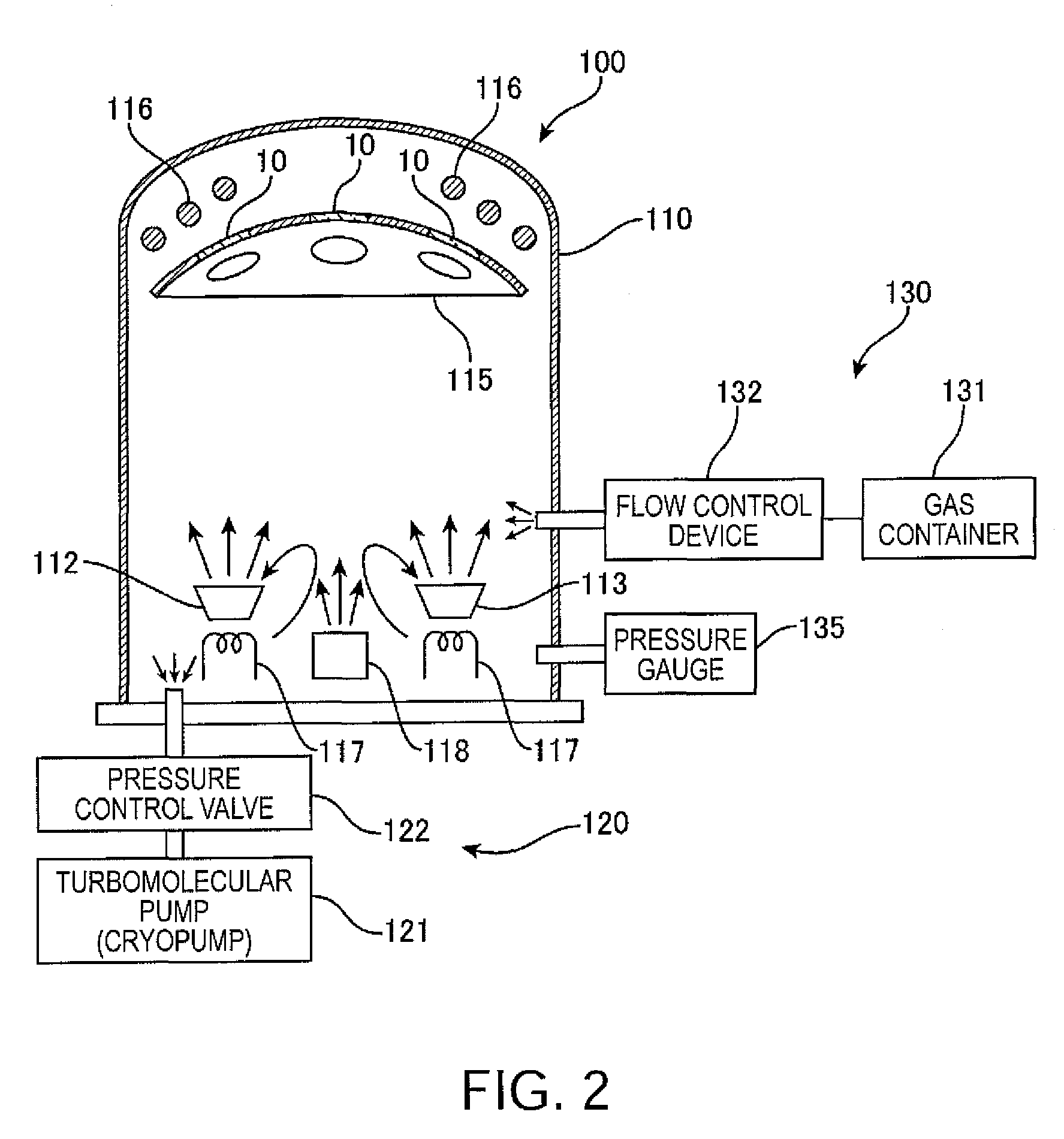
2.1.2.1 Deposition Apparatus

[0058]Subsequently, an inorganic antireflec...

example 2

2.2 Example 2

Sample S2

[0073]Using the same lens substrate 1 as above, a hard coating layer 2 was formed under the same conditions, and an antireflection layer 3 of type A1 was formed on the surface thereof, thereby giving a sample S2. Low-refractive-index layers 31 and high-refractive-index layers 32 were formed under the same conditions as in Example 1 (2.1.2.2). However, in the formation of a silicide layer (fifth layer) 33, a TiSi compound was employed as a deposition source, and the silicide layer 33 was formed by non-ion-assisted vacuum deposition. The silicide layer 33 of the sample 52 was formed to a thickness of 1 nm. After forming the antireflection layer 3, an antifouling layer 4 was formed in the same manner as in Example 1 (see 2.1.3).

example 3

3.1 Example 3

Sample S3

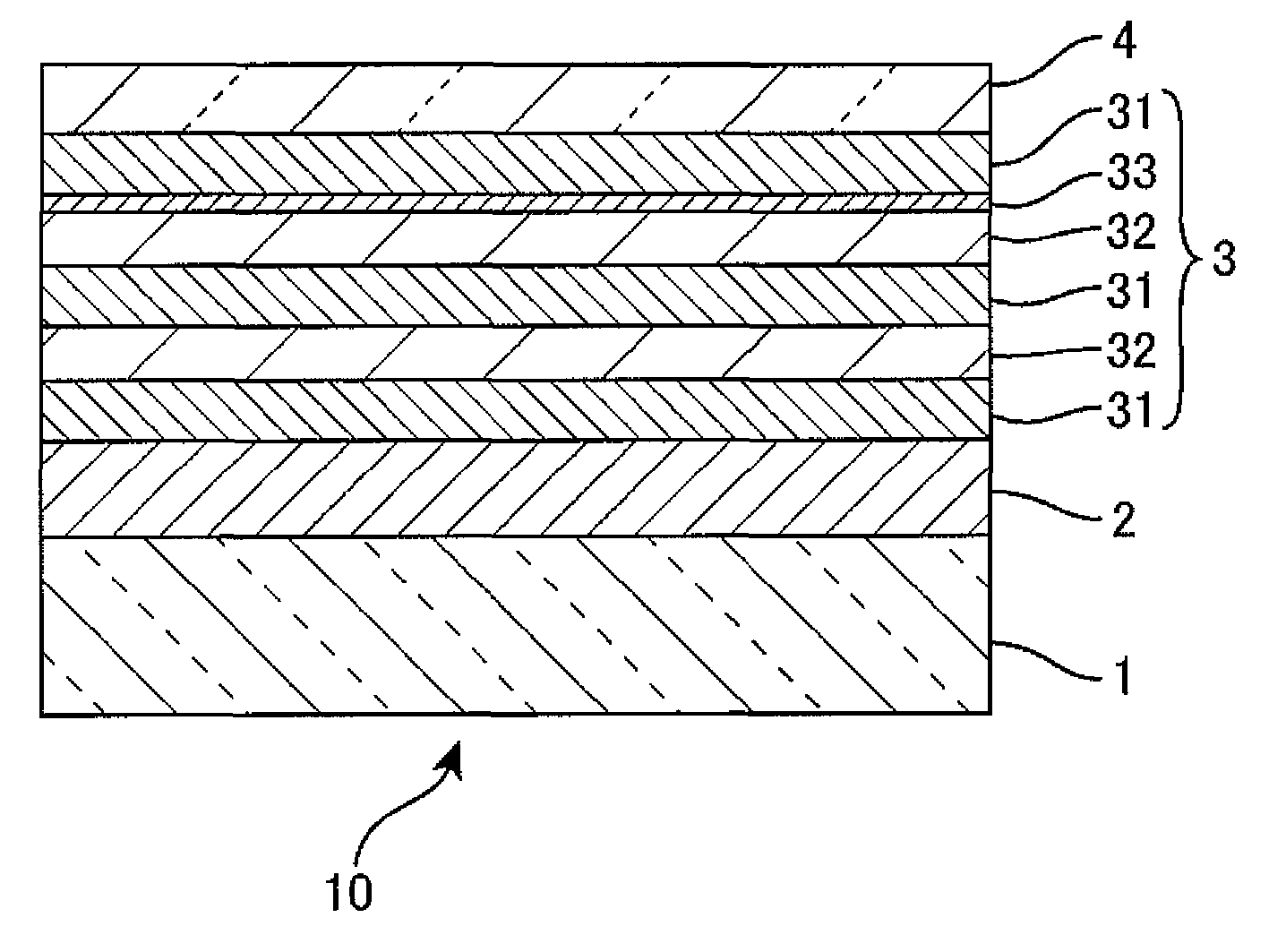
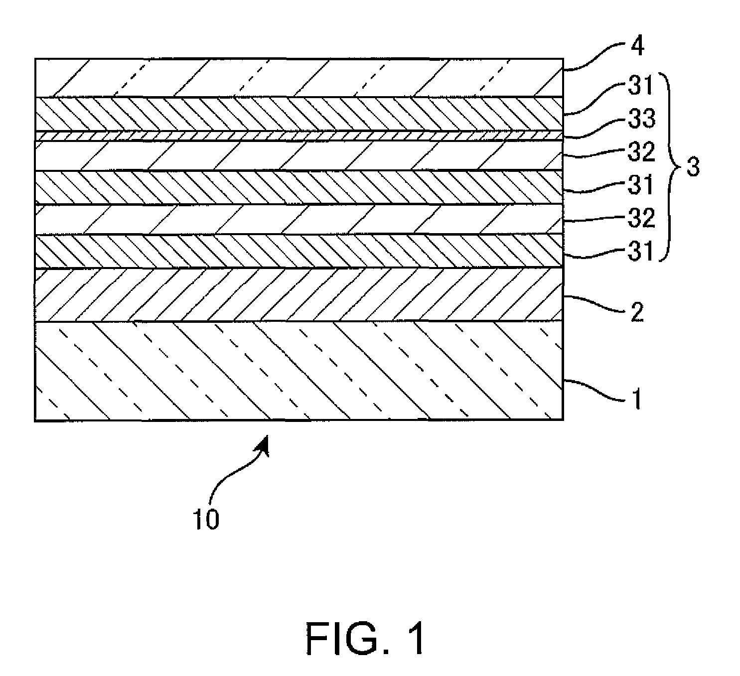
[0091]Using a cover glass as the lens substrate 1, an antireflection layer 3 was formed on the surface thereof, thereby giving a sample S3 of Example 3. The cover glass sample (glass sample) S3 has a transparent clear glass (B270) as the optical substrate 1, and the antireflection layer 3 was formed directly on the optical substrate 1 without forming a hard coating layer. The antireflection layer has the six-layer structure of type A1. That is, the first layer, the third layer, and the sixth layer are low-refractive-index layers 31 of SiO2, the second layer and the fourth layer are high-refractive-index layers 32 of ZrO2, and the fifth layer is a silicide layer 33. The low-refractive-index layers 31 of SiO2 and the high-refractive-index layers 32 of ZrO2 were formed under the same conditions as in Example 1 (2.1.2.2). Meanwhile, the silicide layer 33 was formed under the same conditions as in Example 2 (2.2). The glass sample S3 thus has the antireflection laye...


PUM

PropertyMeasurementUnit
resistivityaaaaaaaaaa
refractive indexaaaaaaaaaa
temperatureaaaaaaaaaa

Abstract

A method for producing an optical article. A first layer that is light-transmissive is formed on an optical substrate directly or with an additional layer in between. A silicide material, light-transmissive thin film is formed on the surface of the first layer.

Description

CROSS-REFERENCE TO RELATED APPLICATIONS[0001]This application claims the benefit of priority under 35 USC 119 of Japanese application no. 2009-005421, filed on Jan. 14, 2009, and Japanese application no. 2009-197787, filed on Aug. 28, 2009, which are incorporated herein by reference.BACKGROUND[0002]1. Technical Field[0003]The present invention relates to an optical article for use as a lens, such as a spectacle lens, or a like optical material or product, and also to a method for producing the same.[0004]2. Related Art[0005]Optical articles, such as spectacle lenses, have a substrate (optical substrate) with various functions and, on the surface of the substrate, layers (films) that perform various functions for enhancing the functions of the substrate and protecting the substrate. Known examples of such layers are a hard coating layer for securing the durability of a lens substrate, an antireflection layer for preventing ghosting and flickering, and the like. A typical antireflecti...

Claims


Application Information

Patent Timeline
Patent Type & Authority Patents(United States)
IPC IPC(8): G02C5/00G02C7/02B32B9/04B05D5/06G02B5/28G02B1/11G02B1/04G02B1/115G02B1/16G02B1/18G02C7/00
CPCC23C14/083G02B27/0018G02B1/115C23C14/5846Y10T428/31504C23C14/10G02B1/041G02B1/10G02B1/11G02C7/02G02C7/088G02C7/10G02B1/18
Inventor NISHIMOTO, KEIJINOGUCHI, TAKASHISEKI, HIROYUKI
Owner HOYA LENS MFG PHILIPPINES
Why Eureka
Try Eureka