Non-astigmatic imaging with matched pairs of spherically bent reflectors

a non-astigmatic imaging and reflector technology, applied in the field of imaging apparatus, can solve the problems of not being able to fully satisfy the analysis of detailed data, the imaging scheme is not readily applicable to other plasma sources, and the image is not fully satisfactory

Inactive Publication Date: 2012-07-10
THE UNITED STATES AS REPRESENTED BY THE DEPARTMENT OF ENERGY
View PDF6 Cites 7 Cited by
  • Summary
  • Abstract
  • Description
  • Claims
  • Application Information

AI Technical Summary

Benefits of technology

[0017]The present invention eliminates the astigmatism encountered in wide angle point-to-point imaging with electromagnetic radiation and ultrasound by using a matched pair of spherically bent reflectors, such as crystals, multilayer structures or minors. This invention is particularly adapted for use in the diagnosis of high energy plasmas by providing imaging schemes with large angles of incidence, which can replace the presently used imaging schemes of near-paraxial rays where expensive detectors and cameras currently must be placed in direct view of an exploding target and are thus at risk of being damaged by debris. In addition for use in detecting and measuring high energy radiation emitted by high temperature plasmas, this invention is also applicable for use with a very broad spectrum of electromagnetic radiation, such as microwaves, infrared and visible light, and UV and EUV radiation, and even to the imaging with ultrasound, if the aforementioned crystals are replaced by appropriate spherical minors. This invention is applicable for use with co-planar reflectors as well as with non-co-planar reflectors.

Problems solved by technology

This imaging scheme is, however, not readily applicable to other plasma sources, where a direction of symmetry or uniform x-ray emission is not provided.
But the images obtained with a single spherically bent crystal from such sources are, in principle, not sharp and flawed by astigmatic errors even if the highest, still practicable, Bragg angles of 80° are used, so that these images are not fully satisfactory for a detailed data analysis.

Method used


Image

  • Non-astigmatic imaging with matched pairs of spherically bent reflectors
  • Non-astigmatic imaging with matched pairs of spherically bent reflectors
  • Non-astigmatic imaging with matched pairs of spherically bent reflectors

Examples


case i

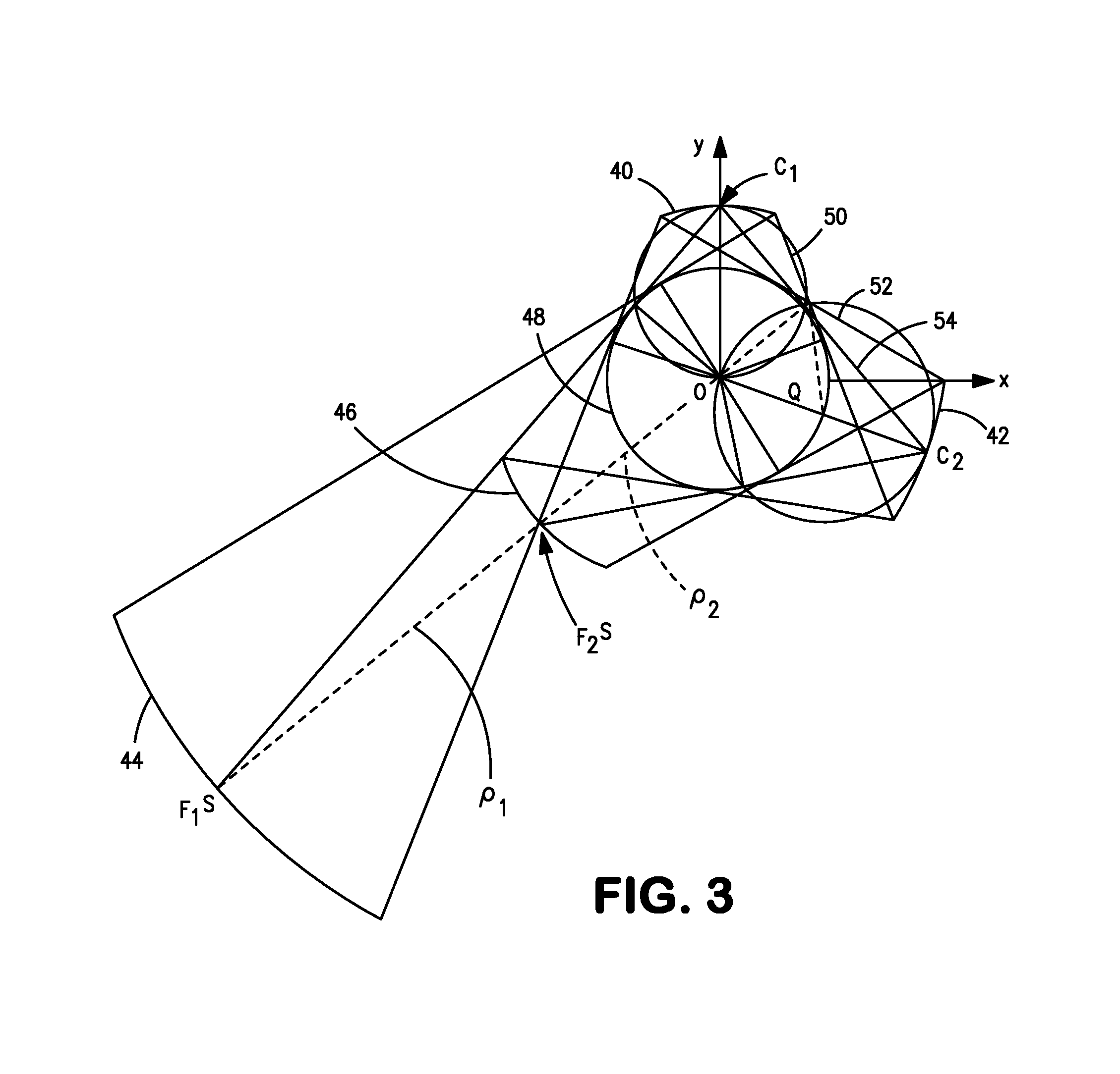
[0029] As shown in FIG. 3, θ1>45° and θ2>45°. In this case, the sagittal images, produced by the two reflectors 40 and 42, are both real, and only the conditions of equations (8) and (9) must be satisfied.

case ii

[0030] As shown in FIG. 4, one of the Bragg angles is smaller and the other larger than 45°, e.g., θ12>45°. In this case, only the sagittal image produced by reflector 62 is real, whereas the sagittal image obtained from reflector 60 is a virtual image Fs, meaning that the sagittal rays reflected by reflector 60 are divergent and appear to emanate from a virtual focus behind the reflector. Therefore, an additional condition, the so-called convergence / divergence condition,

R1 cos(θ1)·tan(2θ1)=−R2 cos(θ2)·tan(2θ2)  (10)

which was already given as equation (6) above, must be satisfied for the rays between the two reflectors. Equation (10) is evidently different from equation (9). However, both conditions can be satisfied if

θ1+θ2=90°  (11)

since then tan(2θ1)=−tan(2θ2).

[0031]We first consider the experimental arrangement which is associated with case I, where both Bragg angles are larger than 45°. FIG. 3 shows a schematic for the parameters: θ1=50°, R1=12.0; θ2=60°, R2=15.4. Here, the valu...


PUM


Abstract

Arrangements for the point-to-point imaging of a broad spectrum of electromagnetic radiation and ultrasound at large angles of incidence employ matched pairs of spherically bent reflectors to eliminate astigmatic imaging errors. Matched pairs of spherically bent crystals or spherically bent multi-layers are used for X-rays and EUV radiation; and matched pairs of spherically bent mirrors that are appropriate for the type of radiation are used with microwaves, infrared and visible light, or ultrasound. The arrangements encompass the two cases, where the Bragg angle—the complement to the angle of incidence in optics—is between 45° and 90° on both crystals/mirrors or between 0° and 45° on the first crystal/mirror and between 45° and 90° on the second crystal/mirror, where the angles of convergence and divergence are equal. For x-rays and EUV radiation, also the Bragg condition is satisfied on both spherically bent crystals/multi-layers.

Description

[0001]The United States Government has rights in this invention pursuant to Contract No. DE-AC02-76CH03073 with the U.S. Department of Energy.FIELD OF THE INVENTION[0002]This invention relates to imaging apparatus for use with electromagnetic radiation of virtually any wavelength and the imaging with ultrasound.BACKGROUND OF THE INVENTION[0003]U.S. Pat. No. 6,259,763 discloses a high-resolution x-ray imaging crystal spectrometer to record spatially resolved impurity line spectra emitted from tokamaks and other extended plasma sources, used in magnetic confinement nuclear fusion energy research, for Doppler measurements of ion temperature and toroidal plasma rotation velocity profiles. The spectrometer concept is based on the Johann configuration, but the typically used cylindrically bent crystal and one-dimensional, position-sensitive detector are replaced by a spherically bent crystal and a two-dimensional, position sensitive detector, whereby spatial resolution or 1d-imaging is ob...

Claims


Application Information

Patent Timeline
Patent Type & Authority Patents(United States)
IPC IPC(8): G01J1/00
CPCG01J3/20G01N29/221B82Y10/00G21K1/062G21K1/06
Inventor BITTER, MANFRED LUDWIGHILL, KENNETH WAYNESCOTT, STEVEN DOUGLASFEDER, RUSSELLKO, JINSEOKRICE, JOHN E.INCE-CUSHMAN, ALEXANDER CHARLESJONES, FRANK
Owner THE UNITED STATES AS REPRESENTED BY THE DEPARTMENT OF ENERGY
Why Eureka
Try Eureka