
Noise-canceling for differential amplifiers requiring no external matching

a technology of differential amplifiers and amplifiers, applied in the field of differential amplifiers, can solve the problems of adding cost to the overall device manufacturing cost, difficult to realize an lna with low noise, and often necessary problems

Active Publication Date: 2012-11-13
QUALCOMM INC
View PDF14 Cites 19 Cited by
  • Summary
  • Abstract
  • Description
  • Claims
  • Application Information

AI Technical Summary

Benefits of technology

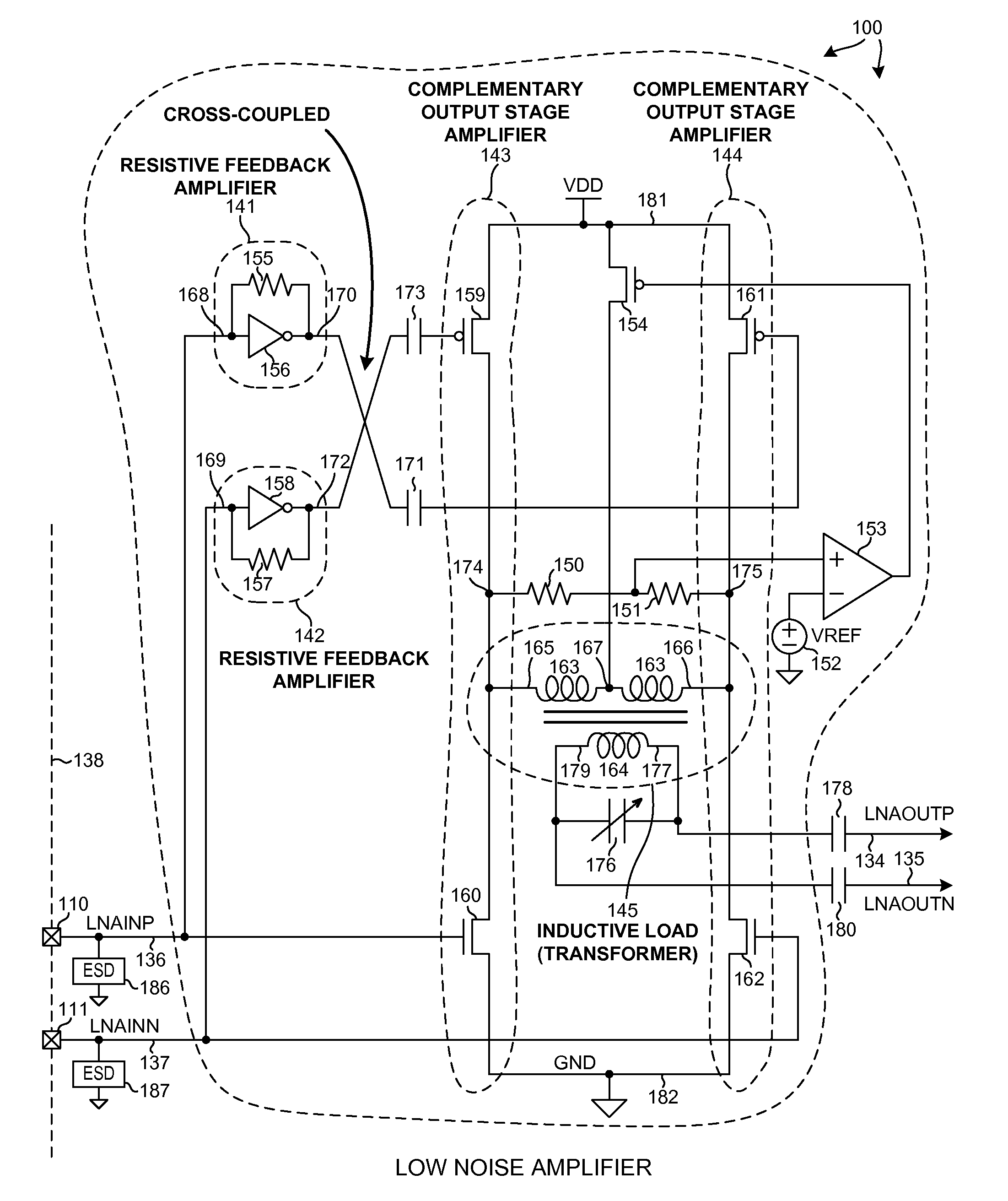
The patent describes a differential Low Noise Amplifier (LNA) that has a unique design and performance. The LNA has a low input impedance, making it suitable for amplifying signals from sources with low impedance without the need for an impedance matching network. The LNA has a high input impedance, making it suitable for amplifying signals from sources with high impedance. The LNA has a low noise factor and a high gain, making it ideal for use in high-speed applications. The LNA has a transformer load with a low input impedance, making it suitable for amplifying signals from sources with low impedance. The LNA has a high input impedance, making it suitable for amplifying signals from sources with high impedance. The LNA has a low noise factor and a high gain, making it ideal for use in high-speed applications. The technical effects of this design include improved signal-to-noise ratios, high bandwidth, and low impedance mismatch requirements.

Problems solved by technology

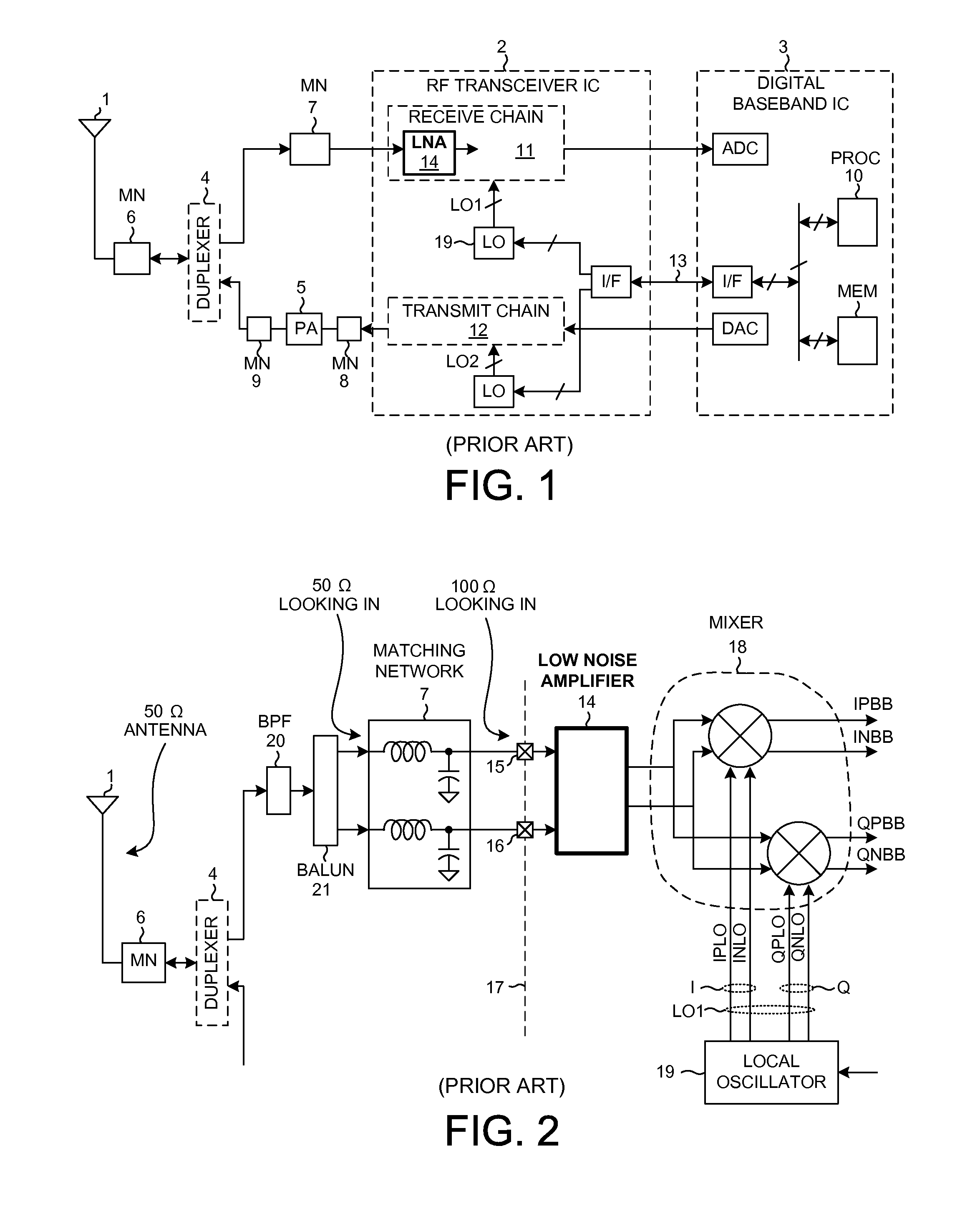
Providing the additional components of matching network 7 generally adds cost to the manufacturing cost of the overall device.
It would be desirable not to have to provide such a matching network, but it is unfortunately often necessary.
It is difficult to realize an LNA that has low noise (noise factor 20 dB), and an input impedance of fifty ohms.
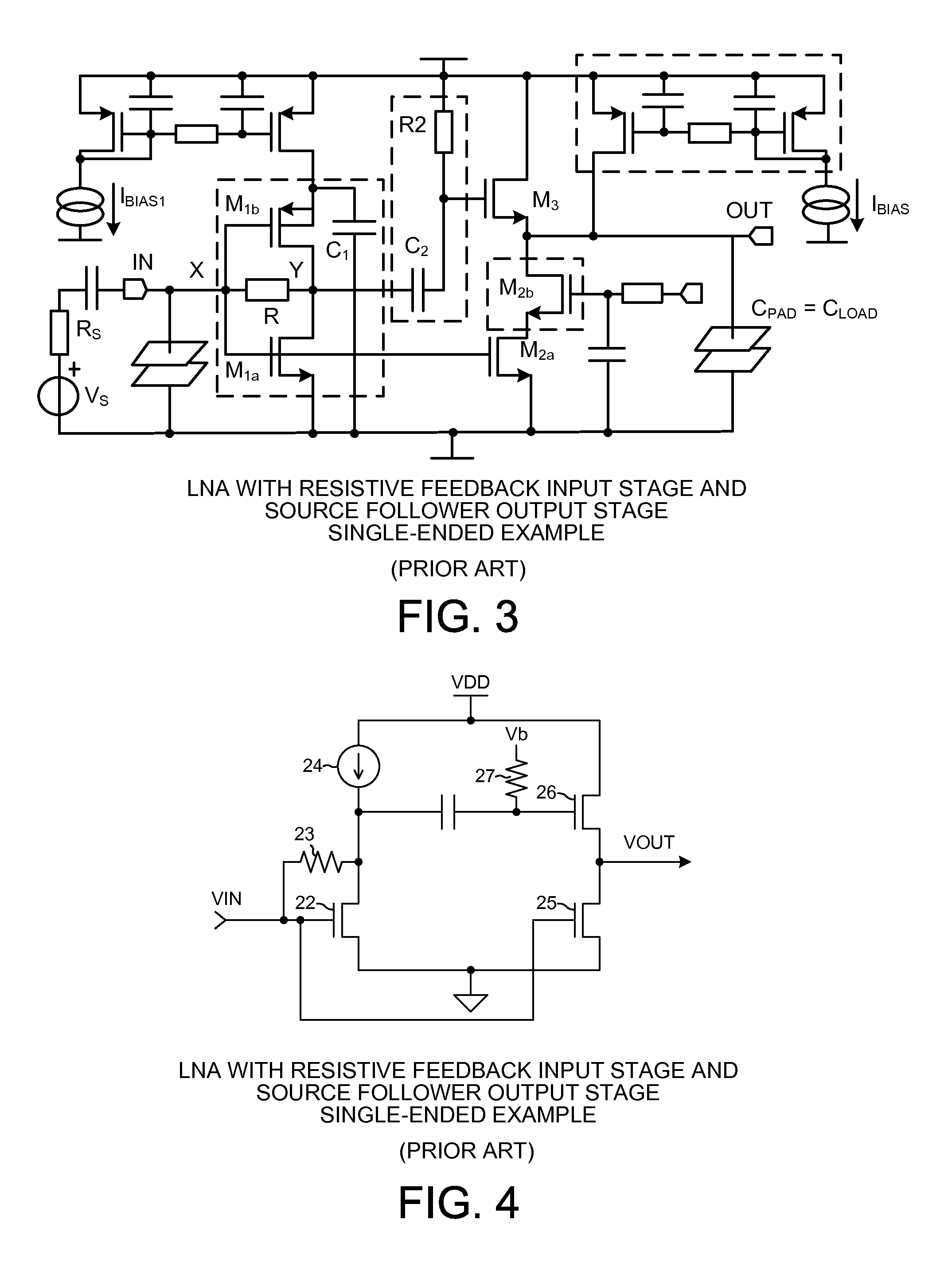
The output impedance of the LNA is low and gain is limited.
The source follower output stage provides rather limited gain.
A disadvantage, however, is that noise from resistor R1 is not canceled.
Moreover, the resistance of R1 is limited by available voltage headroom.
Moreover, a single-ended implementation of the circuit of FIG. 5 is difficult due to the current source at the input.
Consequently, after considering advantages and disadvantages associated with the various known LNA circuits, a design decision is generally made to employ an undesirable and costly matching network such as the matching network 7 of FIG. 1 and FIG. 2 in order to achieve desired LNA performance.

Method used


Image

  • Noise-canceling for differential amplifiers requiring no external matching
  • Noise-canceling for differential amplifiers requiring no external matching
  • Noise-canceling for differential amplifiers requiring no external matching

Examples


Embodiment Construction

[0031]FIG. 7 is a very simplified high level block diagram of one exemplary system that includes a Low Noise Amplifier (LNA) 100 in accordance with one novel aspect. The system is a mobile communication device 101 such as a cellular telephone. Device 101 includes (among other parts not illustrated) an antenna 102 usable for receiving and transmitting cellular telephone communications, an RF transceiver integrated circuit 103, and a digital baseband processor integrated circuit 104.

[0032]FIG. 8 is a more detailed diagram of the RF transceiver integrated circuit 103 of FIG. 7. In one very simplified explanation of the operation of the cellular telephone, if the cellular telephone is being used to receive information as part of a cellular telephone conversation, then an incoming transmission 105 is received on antenna 102. The incoming signal passes through a matching network 106, a duplexer 107, a bandpass filter 108, a balun 109, and into RF transceiver integrated circuit 103 via ter...


PUM


Abstract

A differential Low Noise Amplifier (LNA) includes a first stage of resistive feedback amplifiers and second stage of complementary amplifiers, where the outputs of the first stage are coupled to the inputs of the second stage in a cross-coupled fashion. An inductive load, such as a transformer, combines signals output from the complementary amplifiers of the second stage. In one example, the LNA has an input impedance of less than 75 ohms, a noise factor of less than 2 dB, and a gain of more than 20 dB. Due to the low input impedance, the LNA is usable to amplify a signal received from a source having a similar low impedance without the use of an impedance matching network between the output of the source and the input of the LNA.

Description

BACKGROUND INFORMATION[0001]1. Technical Field[0002]The disclosed embodiments relate to differential amplifiers, and more particularly to high performance differential amplifiers that can be coupled to low impedance sources without intervening matching networks.[0003]2. Background Information[0004]The first stage in a receiver is often an amplifier referred to as a Low-Noise Amplifier or “LNA”. FIG. 1 (Prior Art) is a simplified block diagram of a device that employs such an LNA. The device is a mobile communication device (for example, a cellular telephone handset) and includes an antenna 1, an analog Radio Frequency (RF) transceiver integrated circuit 2, a digital baseband processor integrated circuit 3, a duplexer 4, a power amplifier 5, and a number of matching networks 6-9. A processor 10 in the digital baseband processor integrated circuit 3 controls the RF transceiver 2 by sending control communications to a receive chain 11 and to a transmit chain 12 of the RF transceiver in...

Claims


Application Information

Patent Timeline
Patent Type & Authority Patents(United States)
IPC IPC(8): H03F3/45
CPCH03F3/3081H03F3/189H03F3/30
Inventor BEHERA, MANASMUTHALI, HARISH SBARNETT, KENNETH CHARLES
Owner QUALCOMM INC
Learn More