Metallization film capacitor having divided electrode with fuse

a technology fuse, which is applied in the direction of wound capacitor, fixed capacitor details, fixed capacitors, etc., can solve the problems of low heat resistance of a conventional metallization film capacitor, inability to achieve high temperature resistance, and extremely long service life of metallization film capacitors. achieve the effect of high heat resistance, better self-maintenance performance, and high withstand voltag

Inactive Publication Date: 2012-11-13
PANASONIC CORP
View PDF27 Cites 55 Cited by
  • Summary
  • Abstract
  • Description
  • Claims
  • Application Information

AI Technical Summary

Benefits of technology

[0013]The present invention solves the above disadvantage of the prior art, and offers a metallization film capacitor that can achieve both high heat resistance and high withstand voltage at the same time, compared to the conventional metallization film capacitor using a PP film.
[0015]The metallization film capacitor of the present invention is configured to achieve deposition pattern pass rate a / b of not greater than 4.0, where ‘a’ is the width of the fuse and ‘b’ is the length of divisional electrode in the lengthwise direction of the metalized film. In other words, a narrower fuse and a wider divisional electrode can cut off an area by pinpointed evaporation of the metal-deposited electrode by less energy in the metallization film capacitor configured with the metal-deposited electrode on the dielectric film containing inorganic filler. Accordingly, the present invention achieves better self-maintaining performance, and better withstand voltage.

Problems solved by technology

In addition, metallization film capacitors have an extremely long service life, so they also tend to be adopted on the market for reasons of low maintenance.
However, the heat resistance of a conventional metallization film capacitor is low (about 110° C.) because it generally uses a polypropylene film (hereafter referred to as a “PP film”) for its dielectric film.
This does not achieve resistance to the high temperature (150° C.) needed for vehicles.
However, if a PEN film is used, sufficient heat resistance is achieved, but the withstand voltage is low.
Performance of withstand voltage is not sufficient even if electrode patterns are formed by metal deposition, a technology built on the use of conventional PP film.Patent Document 1: Japanese Patent Unexamined Publication No.

Method used


Image

  • Metallization film capacitor having divided electrode with fuse
  • Metallization film capacitor having divided electrode with fuse
  • Metallization film capacitor having divided electrode with fuse

Examples


first exemplary embodiment

[0024]The first exemplary embodiment of the present invention is described below.

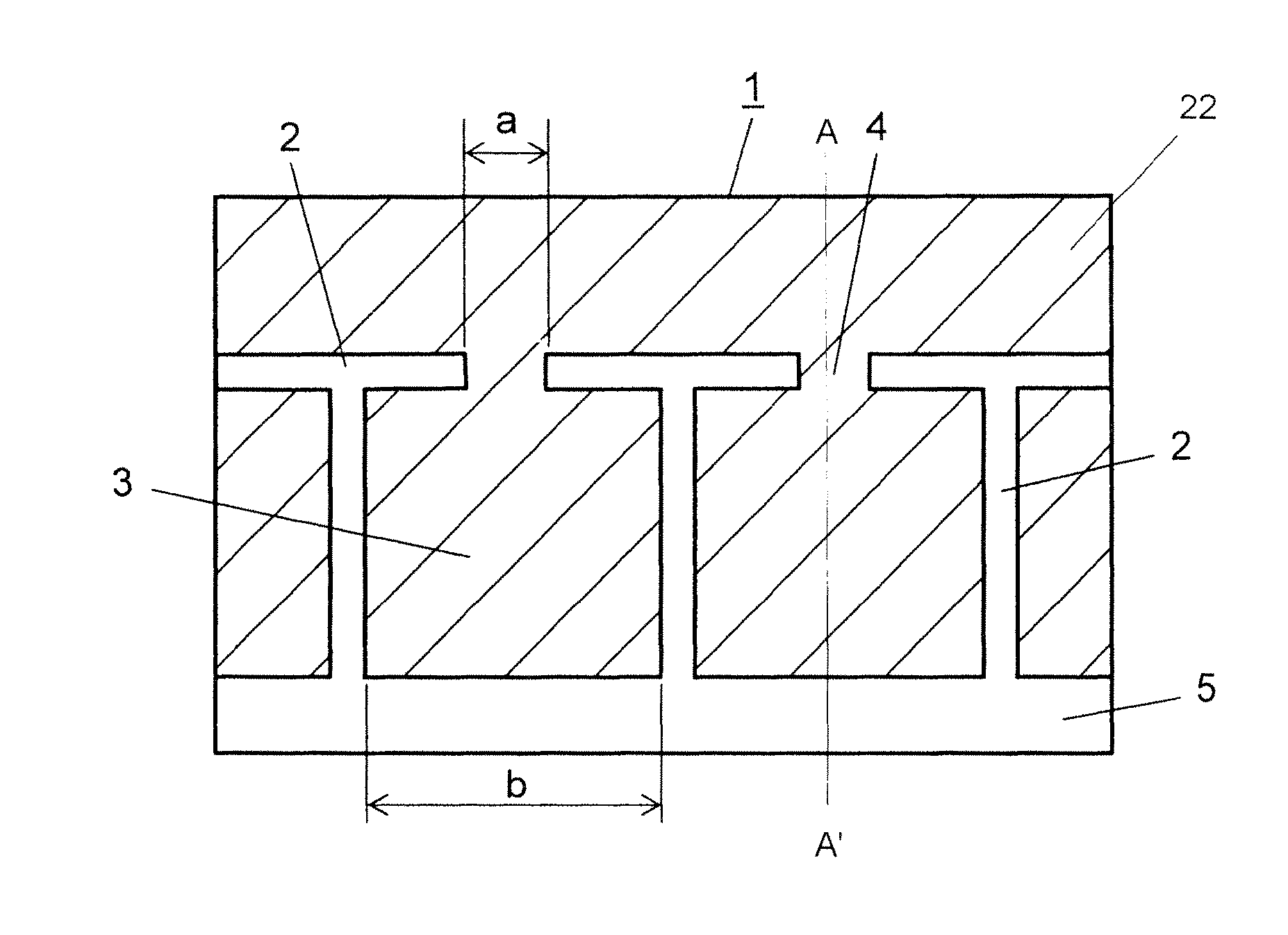
[0025]FIG. 1 is a plan view of a key part illustrating a structure of a metalized film used in a metallization film capacitor in the first exemplary embodiment of the present invention, and FIG. 5 is a cross sectional view of the A-A line of FIG. 1. In FIG. 1, metalized film 1 includes a strip of polyethylene naphthalate film 20 containing inorganic filler 21 (hereafter referred to as a “PEN” film) 2.0 μm thick and 30 mm wide as a dielectric film. Slit 2, which is a non-metal deposited portion, is provided on a surface of this PEN film, and aluminum metal-deposited electrodes are formed to create multiple divisional electrodes 3. These divisional electrodes 3 are coupled in parallel by using fuse 4. Metalized film 1 also includes margin 5, which is a non-metal deposited portion. Further, the metal-deposited electrode includes a current collective portion 22.

[0026]A pair of metalized films 1 as configure...

second exemplary embodiment

[0038]The second exemplary embodiment of the present invention is described below.

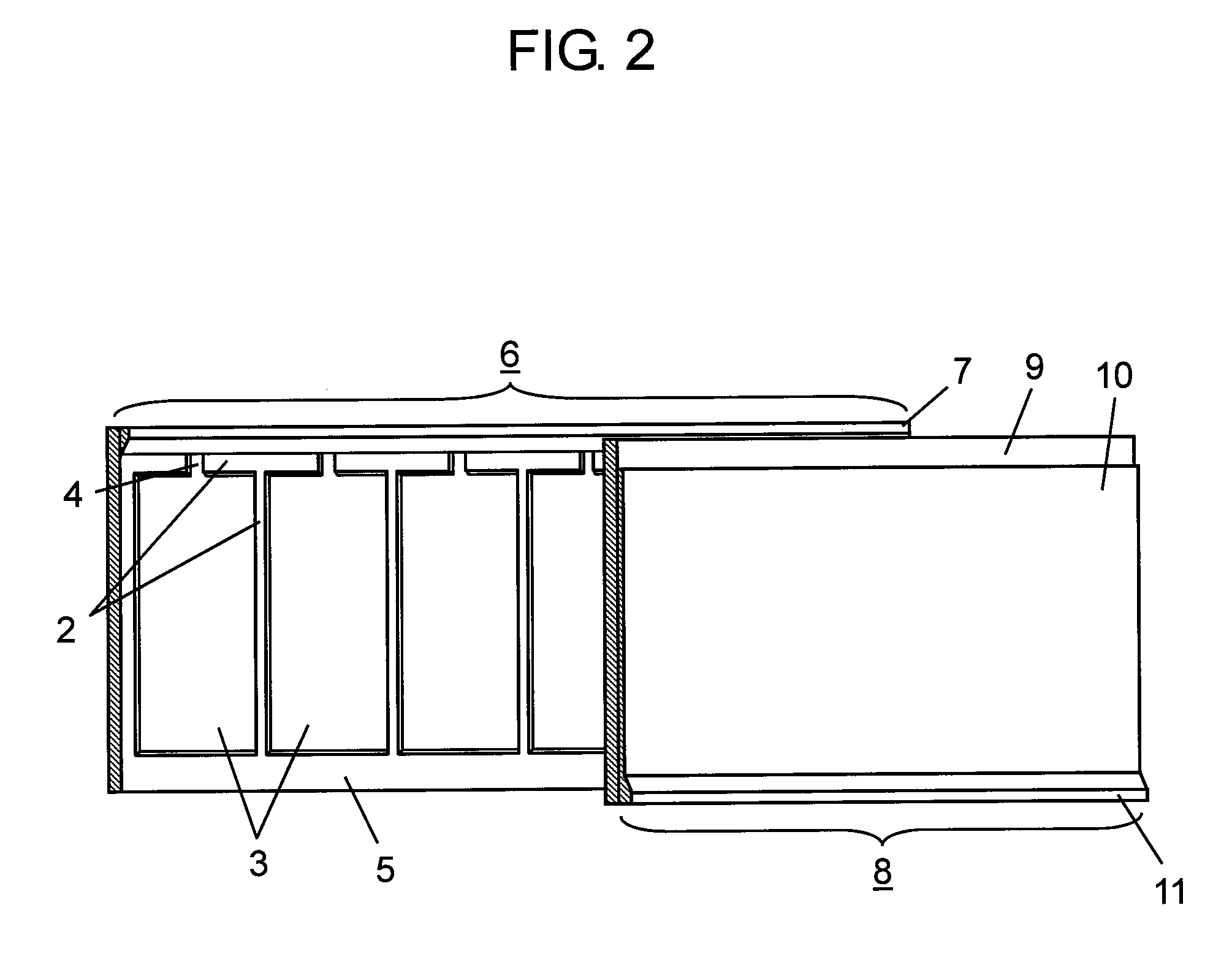
[0039]The second exemplary embodiment has a partially different structure for the metal-deposited electrode formed on the metalized film used in the metallization film capacitor, compared to that of the first exemplary embodiment described with reference to FIG. 1. Other components are the same as the first exemplary embodiment, and thus the same reference marks are given to omit their duplicate description. Only the point that differs is detailed below with reference to a drawing.

[0040]FIG. 2 is a plan view of a key part of a pair of metalized films in an overlaid state in a metallization film capacitor in the second exemplary embodiment of the present invention. In FIG. 2, same as metalized film 1 described in the first exemplary embodiment, first metalized film 6 has slit 2, which is a non-metal deposited portion, and aluminum metal-deposited electrodes to create multiple divisional electrodes 3. Th...

third exemplary embodiment

[0047]The third exemplary embodiment of the present invention is described below.

[0048]FIG. 3A is a perspective view of an element of a metallization film capacitor in the third exemplary embodiment of the present invention. FIG. 3B is a front view of a defective core of the element, and FIG. 3C is a front view of another defective core of the element. In FIGS. 3A to 3C, ‘A’ is a longer diameter of elliptically wound element 12 using a PEN film for a dielectric film, and ‘B’ is a shorter diameter.

[0049]In element 12 as configured above, cylindrical core 13 is first prepared, and the metalized film described in the first exemplary embodiment or the second exemplary embodiment is wound around this core 13, after which this cylindrical element 12 is pressed to form an oblate shape.

[0050]In this element 12, both ends of core 13 will be acute-angled, as shown in FIG. 3B, if core 13 is thin. Accordingly, the metalized film near this acute-angled portion will also be curved in an acute-ang...


PUM


Abstract

A metallization film capacitor that achieves both high heat resistance and high withstand voltage at the same time. A metal-deposited electrode is formed on a PEN film in each of a pair of metalized films. These metalized films are wound such that the metal-deposited electrodes face each other via the dielectric film in between. A metalized contact electrode is formed on both end faces of these wound metalized films to configure the metallization film capacitor. A divisional electrode is provided on the metal-deposited electrode. In addition, a fuse is coupled to this divisional electrode for providing a self-maintaining function. Pass rate a / b of a deposition pattern is set to 4.0 or smaller, where ‘a’ is the fuse width, and ‘b’ is the length of the divisional electrode in a lengthwise direction of the metalized films.

Description

RELATED APPLICATIONS[0001]This application is the U.S. National Phase under 35 U.S.C. §371 of International Application No. PCT / JP2007 / 066514, filed on Aug. 27, 2007, which in turn claims the benefit of Japanese Application No. 2006-230078, filed on Aug. 28, 2006, the disclosures of which Applications are incorporated by reference herein.TECHNICAL FIELD[0002]The present invention relates to metallization film capacitors employed in a range of electronic devices, electrical equipment, industrial equipment, and vehicles, and more particularly to metallization film capacitors suitable for smoothing, filtering, and snubbing in motor-driving inverter circuits of hybrid vehicles.BACKGROUND ART[0003]Inverter circuits are increasingly being used to control a wide variety of electrical equipment to conserve energy and achieve high efficiency from the viewpoint of environmental protection. In particular, in the car industry, the development of technologies for conserving energy and improving ...

Claims


Application Information

Patent Timeline
Patent Type & Authority Patents(United States)
IPC IPC(8): H01G2/00H01G4/08
CPCH01G4/015H01G4/18H01G4/32Y02T10/7022Y02T10/70H01G4/33
Inventor FUJII, HIROSHIKYOUDA, TAKUYATAKEOKA, HIROKI
Owner PANASONIC CORP
Why Eureka
Try Eureka