
Multiple axes scanning system and method for measuring radiation from a radiation source

a scanning system and radiation source technology, applied in the field of multiple axes scanning systems, can solve the problems of not being new concepts, exceeding the capabilities of most if not all commercially available scanners, and few commercial scanning systems are capable of scanning the full diagonal plus 5 cm over-scan, etc., and achieve the effect of improving the method of beam scanning confiden

Active Publication Date: 2012-11-27
SUN NUCLEAR
View PDF65 Cites 34 Cited by
  • Summary
  • Abstract
  • Description
  • Claims
  • Application Information

AI Technical Summary

Benefits of technology

[0027]The present invention also provides an improvement in a method of mounting the radiation detector with an offset from the center of the scan axis which enables full access to the tank edge, thereby extending the scanning range and eliminating the need to shift the system (scanner and / or tank) when scanning large field sizes. In particular to the embodiment herein described by way of example with a 66 cm inner diameter tank, it becomes possible to scan the largest field size (40 cm×40 cm at isocenter, to the axes and diagonals, as addressed above) in two segments per profile with their scan centers offset on either side from the ring drive center. The segments can be scanned with both directions without user intervention by a ring rotation, or the user can reposition the offset mount and rescan in the same direction. The present invention provides further improvement with reference detector and one or more radiation detectors wherein the multiple detectors, connected to electronic means, are mounted at various points on the scan axis, offset on both sides of the axis center as well as the possibility of one detector on the axis center, enabling the full field scan in one scan of the detectors. The overlapping scan regions provide means by which analysis means may normalize and concatenate partial scans of all detectors into one field scan.
[0029]The present invention provides an improvement in a method of profile analysis that determines the beam penumbra from the scanned penumbra by de-convolution of the scanned detector response, where the de-convolution method uses the chamber spread function that is determined in these analysis means from data measured with the scanning detector that exhibits penumbra spreading and another detector that does not exhibit significant penumbra spreading, both scanned with these scanning means. The present invention provides an improvement in the method of confidence in beam scanning by providing analysis means that may calculate ratios of normalized orthogonal scanned beam profiles, resulting in a values (plot) of the radial homogeneity of the radiation field, and provides a comparison of the penumbra shape that is characteristic to beam shapers such as jaw positions (upper and lower), MLC leaf ends and leaf sides, as two examples. Ratios of percent depth dose curves (PDD) may be calculated, normalized at same depth, measured at different beam energies, resulting in values that trend up or down, depending upon the actual beam energy, thereby providing comparison means with expected trend. Given the same field size, higher beam energy PDD divided by lower beam energy will produce values than trend upward, i.e., increase in value with increase in depth. Ratios of normalized profiles measured with the same beam geometry but measured at different times in the queuing process may be calculated, resulting in a values (plot) that that should not change if no physical setup changes occurred, no physical operating conditions of the scanning system occurred, no changes in the LINAC radiation delivery occurred. Analysis of these ratio values will reveal slight shifts in the scanner reference position by causing differences in the penumbra regions, changes in the beam limiters, changes in the LINAC beam shape, to name a few. Ratios of normalized scans (profiles and PDD curves) may be calculated that have corresponding LINAC setup conditions that were measured in a reference set of LINAC measurements that are known to be good, i.e., golden or benchmark data. Such a data set was determined by Sun Nuclear Corp under an SBIR contract “Establishment of Benchmark Data Sets for Radiotherapy Quality Assurance” with the National Institute of Health's National Cancer Institute Contract No. HHSN261200522014C, ADB Contract No. N43-CM-52214.

Problems solved by technology

In practical terms, however, very few commercial scanning systems are capable of scanning the full diagonal plus 5 cm over-scan at depths of >30 cm for 40×40 cm2 field at 100 cm SSD.
The guidelines, although published in 2008, are not new concepts since the 40 cm field sizes and TPS requirements have been around for decades.
This exceeds the capabilities of most if not all commercially available scanners.
However, the scan dimensions are typically limited by the mechanical overhead of pillow blocks and stops that restrict the scan dimensions to approximately 54 cm×50 cm and 40.8 cm depth.
Some of the scanners have this provision with a detector mount that can be rotated, but this requires a trip into the LINAC room and runs the risk of disturbing the setup.
It would keep the detector properly oriented but with the burden of a trip into the room and disturbance of the scanner setup.
However, this “de-convolutioncorrection method is complex and typically not available in the scanning systems.
During these many setup changes and tedious measurements, the operator may incorrectly identify data with particular setups.
These types of setup errors are difficult to see after the sessions have ended and the data saved.
The operator can open the data and examine the profiles, but there is generally not enough characteristic uniqueness to the data to easily identity an error, particularly if the operator is not very experienced, or even with experienced operators, when the error is a collimator rotation of 90 degrees.

Method used


Image

  • Multiple axes scanning system and method for measuring radiation from a radiation source
  • Multiple axes scanning system and method for measuring radiation from a radiation source
  • Multiple axes scanning system and method for measuring radiation from a radiation source

Examples


Embodiment Construction

[0042]The present invention will now be described more fully hereinafter with reference to the accompanying drawings, in which embodiments of the invention are shown. This invention may, however, be embodied in many different forms and should not be construed as limited to the embodiments set forth herein. Rather, the embodiments herein presented are provided so that this disclosure will be thorough and complete, and will fully convey the scope of the invention to those skilled in the art.

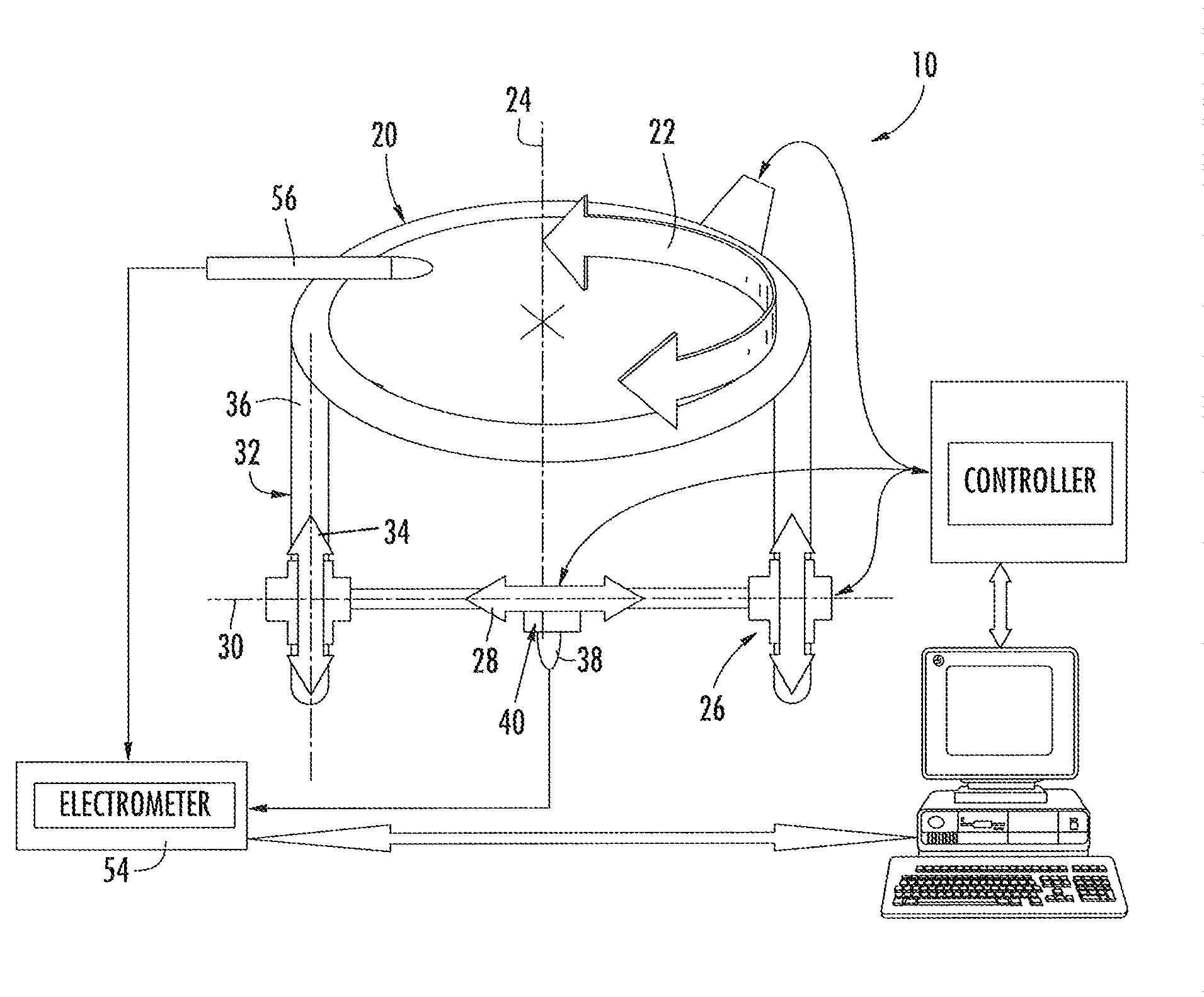
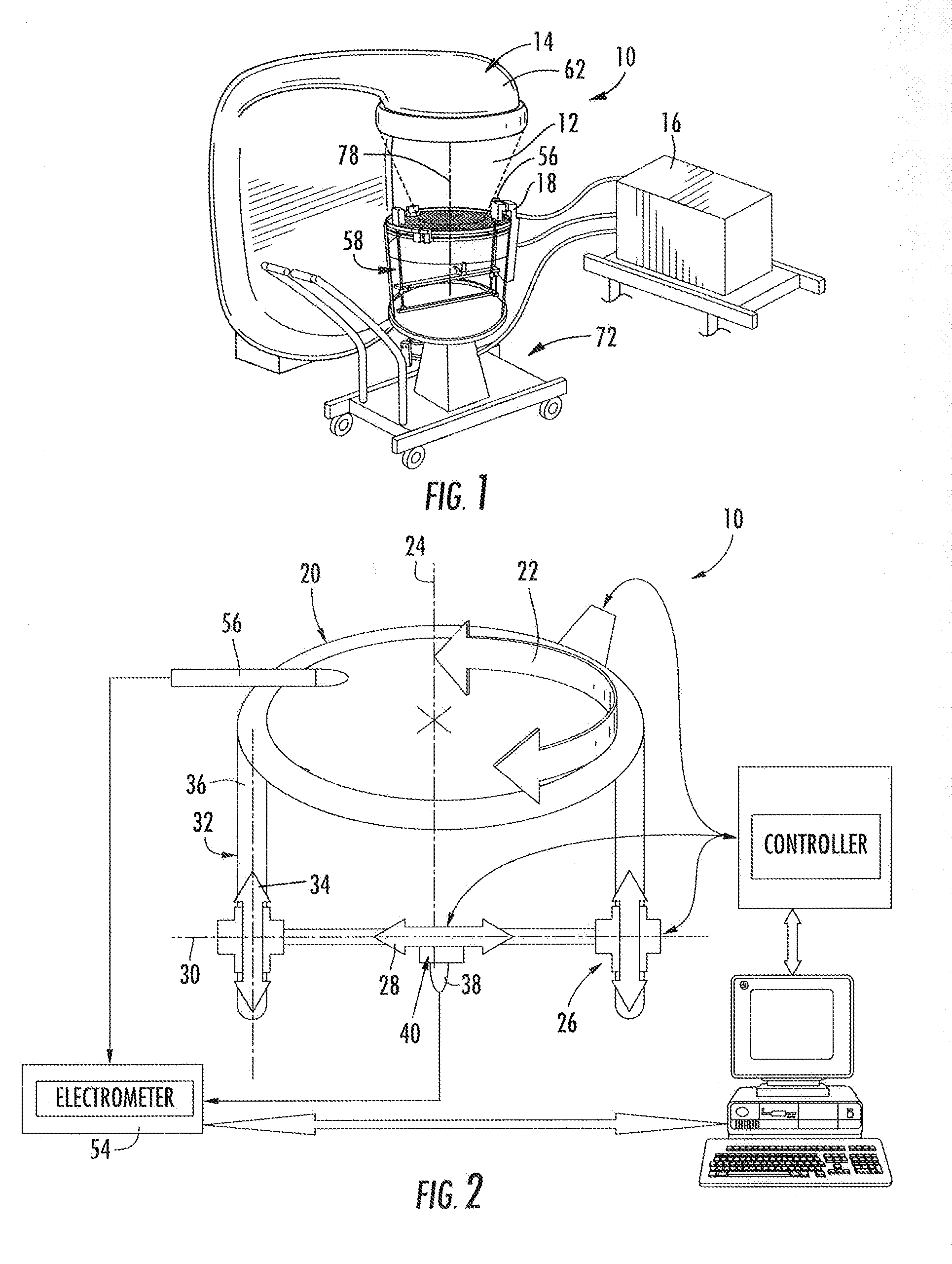
[0043]By way of example, and with reference initially to FIG. 1, one embodiment of the invention, herein described by way of example, is a multiple axes scanning system 10 for measuring radiation 12 emitted from a radiation source 14. The system 10 comprises a processor 16 having analysis and data storage capabilities and a controller 18 operable with the processor.

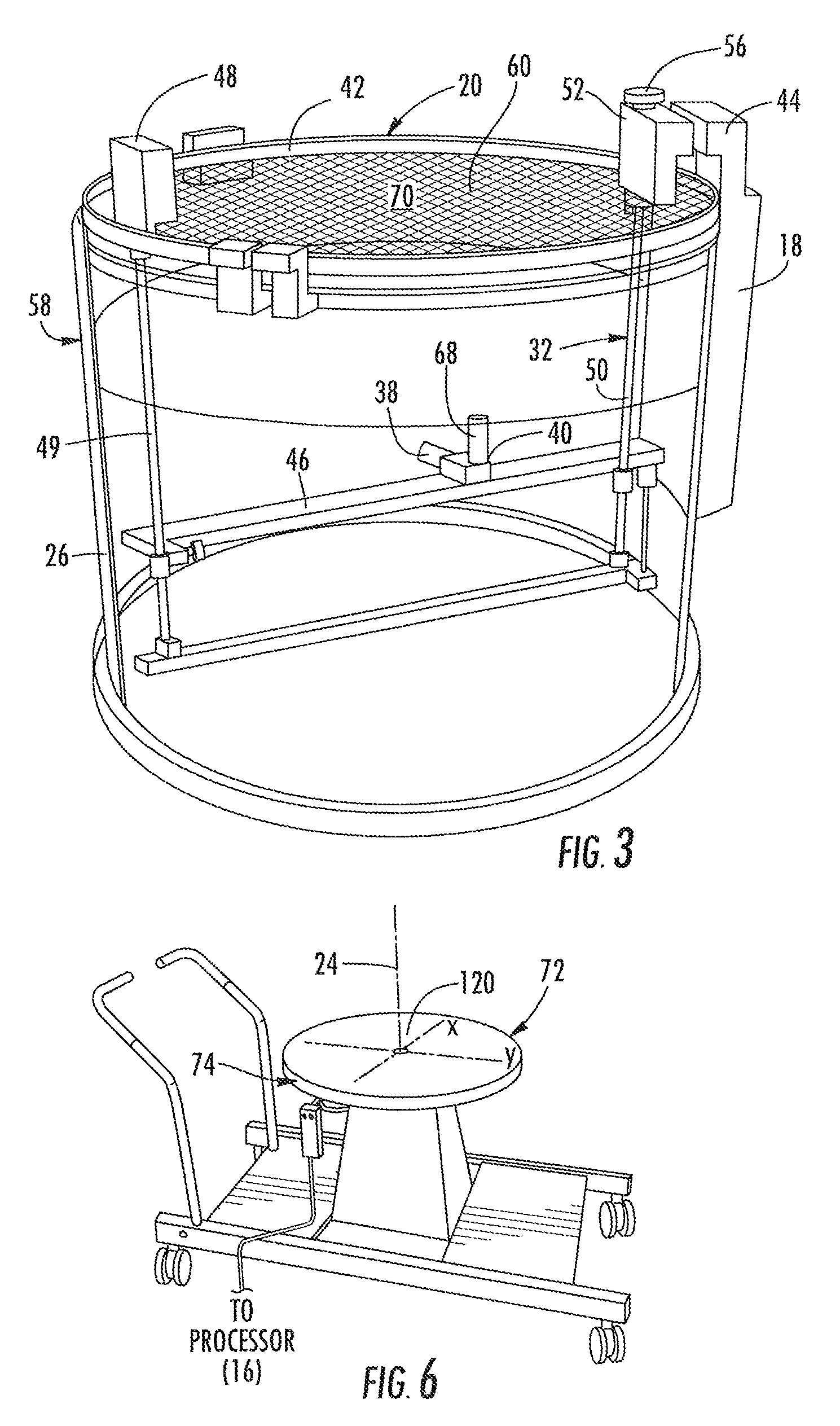
[0044]With reference to FIG. 2, a ring drive 20 is operable with the controller 18 for providing a rotational movement 22 about a first...


PUM


Abstract

A three dimensional radiation measurement scanning system includes a circular drive operable with horizontal and vertical drives for moving a radiation detector through first, second and third orthogonal axes in a three dimensional scanning of the detector in a water tank. Motor are coupled to the drives and activated by a controller for providing the movement of the radiation detector which providing radiation field sensing signals for locations of the detector throughout the tank. A reference detector is fixed for comparing its radiation field measurements with those of the scanned radiation detector. An offset mount carries the radiation detector allowing it to be extended beyond the circular ring gear during horizontal movement of the radiation detector and thus position the radiation detector at wall surfaces of the water tank.

Description

CROSS REFERENCE TO RELATED APPLICATION[0001]This application claims priority to Provisional Application Ser. No. 61 / 227,841 having filing date of Jul. 23, 2009 for “Three Dimensional Dosimetry Scanning System and Method Using Cylindrical Geometry,” the disclosure of which is herein incorporated by reference in its entirety, and commonly owned.FIELD OF INVENTION[0002]The invention generally relates to radiation therapy equipment and radiation treatment, and in particular to systems and methods for measuring and localizing, spatially and / or temporally, the dose in a phantom for commissioning treatment planning systems in radiation therapy beam delivery.BACKGROUND[0003]Best standard practice for commissioning a linear accelerator for clinical use typically requires a three dimensional (3D) water tank dosimetry scanner (3DS). A 2008 AAPM report1 “Accelerator Beam Data Commissioning Equipment and Procedures: Report of the TG-106 of the Therapy Physics Committee of the AAPM” (Indra Das—Ch...

Claims


Application Information

Patent Timeline
IPC IPC(8): G01T1/00
CPCA61N5/10A61N5/1048A61N5/1082A61N5/1075A61N2005/1076
Inventor SIMON, WILLIAM E.ROSE, MARKWATTS, RONALD J.BRECHBILL, SETHAUSTHOF, WILLIAMSIMON, THOMAS ALLANKOZELKA, JAKUB
Owner SUN NUCLEAR
Learn More