Image sensing apparatus and image data correction method

a technology of image sensing apparatus and image data, which is applied in the direction of instruments, television systems, optical elements, etc., can solve the problems of deterioration of image quality that is principally caused by optical systems, chromatic aberration reduction, and reduction of the quantity of light in the periphery, so as to quickly correct the deterioration of image quality and expand the configuration of the apparatus.

Active Publication Date: 2013-01-08
CANON KK
View PDF14 Cites 4 Cited by
  • Summary
  • Abstract
  • Description
  • Claims
  • Application Information

AI Technical Summary

Benefits of technology

[0013]The present invention has been made in consideration of the above situation, and the present invention makes it possible to quickly correct deterioration of image quality due to optical factors that has complex point asymmetry without enlarging the configuration of the apparatus.
[0017]Furthermore, according to the present invention, provided is an image data correction method of an image sensing apparatus, the image sensing apparatus including a control unit that controls an optical member by using a parameter, an image sensing unit that generates image data from an object image formed via the optical member, and a storage unit that stores, with respect to a plurality of setting values assumable by the parameter for controlling the optical member, correction information for correcting deterioration of image quality of image data that is caused by characteristics of the optical member and that is point asymmetrical with respect to an optical axis of the optical member, the correction information corresponding to a plurality of image heights at a plurality of polar angles in a polar coordinate system centered on the optical axis of the optical member, the method comprising the steps of: when the control unit controls the optical member by using the parameter, reading correction information corresponding to a plurality of setting values that are close to a setting value of the parameter used by the control unit from the correction information stored in the storage unit; converting a pixel position of the image data generated by the image sensing unit to polar coordinates centered on the optical axis of the optical member; generating correction information that corresponds to the setting value of the parameter used by the control unit and the polar coordinates converted in the converting step by interpolating the correction information read in the reading step; correcting the image data at the pixel position at the polar coordinates by using the correction information generated in the generation step; and detecting a feature amount for each region of the image data generated by the image sensing unit, wherein the reading step comprises reading more correction information with respect to a range having a larger feature amount detected in the feature detection step from among the correction information stored in the storage unit.

Problems solved by technology

On the other hand, deterioration of images due to pixel size reduction, and deterioration of image quality that is principally caused by the optical system, such as reduction in the quantity of light in the periphery of an image circle, magnification chromatic aberrations and distortion aberrations, due to factors such as difficulty in designing small lenses, are becoming more noticeable.
However, the actual images are affected by the characteristics of a lens that is constituted by a plurality of lens groups, the shape of optical members, such as a diaphragm mechanism, as well as the physical structure of sensors, and thus the deterioration of image quality does not always have point symmetrical phenomenal characteristics.
In addition, it is also necessary to give consideration to the fact that the memory capacity required to store correction characteristics data for correcting the above-described point asymmetrical deterioration of image quality, and resources such as the processing time of correction characteristics data are limited and few in the case of image sensing using a camera or a video camera.
However, this technique only similarly changes basic correction characteristics using the distance gain functions.
Accordingly, for optical characteristics having complex point asymmetry, it is necessary to have complex distance gain functions, and appropriate correction effects cannot be obtained since this technique cannot cope with shape changes that are dissimilar.
Furthermore, approximating correction characteristics for changes in optical parameters and image height position with a simple model does not actually achieve an appropriate correction process.
However, in this example, the discretely disposed correction information is used without being processed, and thus for optical characteristics having complex point asymmetry, there is no way but to simply increase the density of the correction information.
However, in this example, the asymmetry of the entire screen is expressed by synthesizing line-symmetrical phenomenal characteristics so that they can be expressed by a specific function, and thus this technique cannot cope with optical characteristics that change in an angular direction with respect to the center of the optical axis.
In addition, it is realistically impossible to perform the same process in the state of actual image sensing in which the optical parameters successively change.

Method used


Image

  • Image sensing apparatus and image data correction method
  • Image sensing apparatus and image data correction method
  • Image sensing apparatus and image data correction method

Examples


embodiment 1

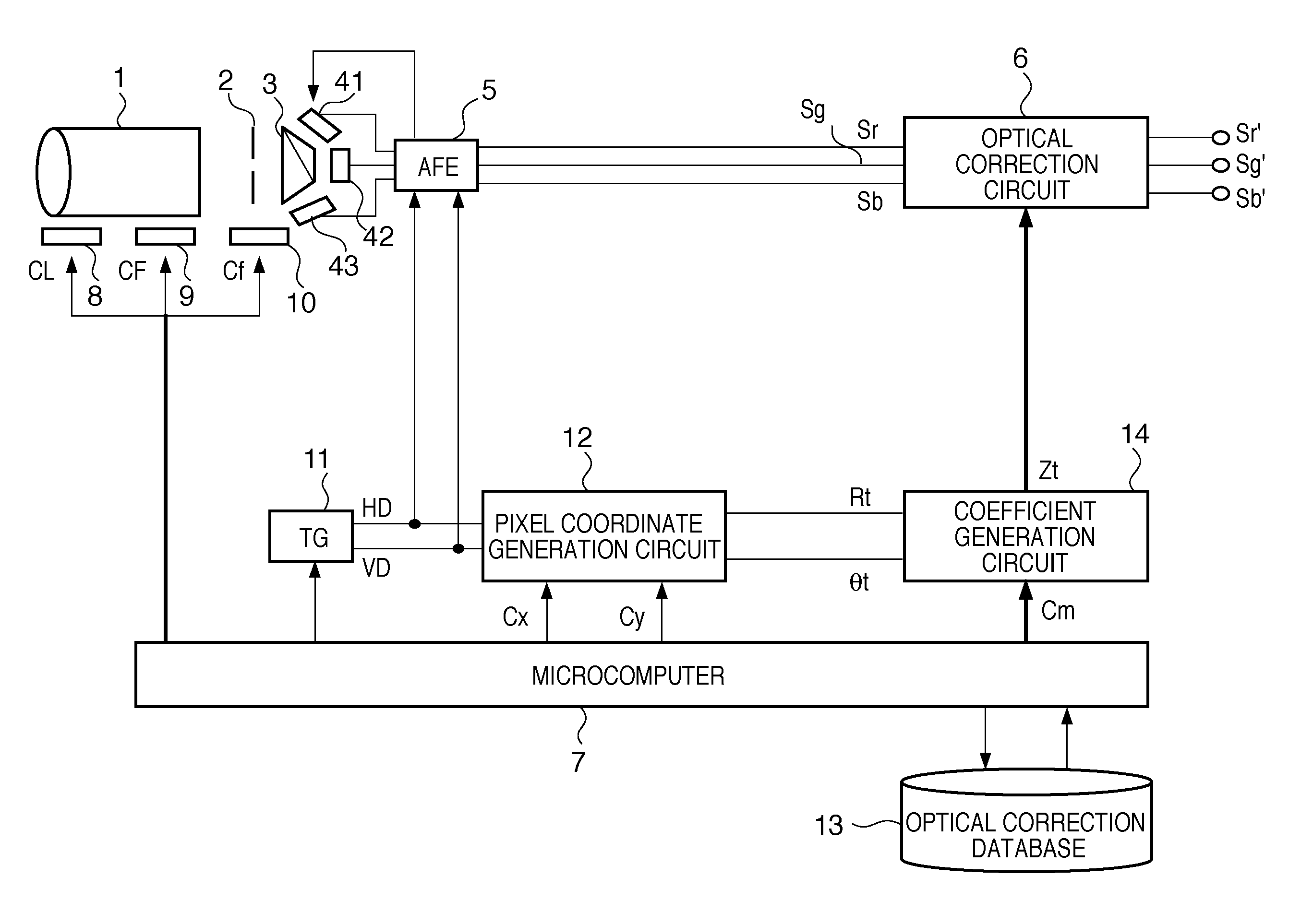
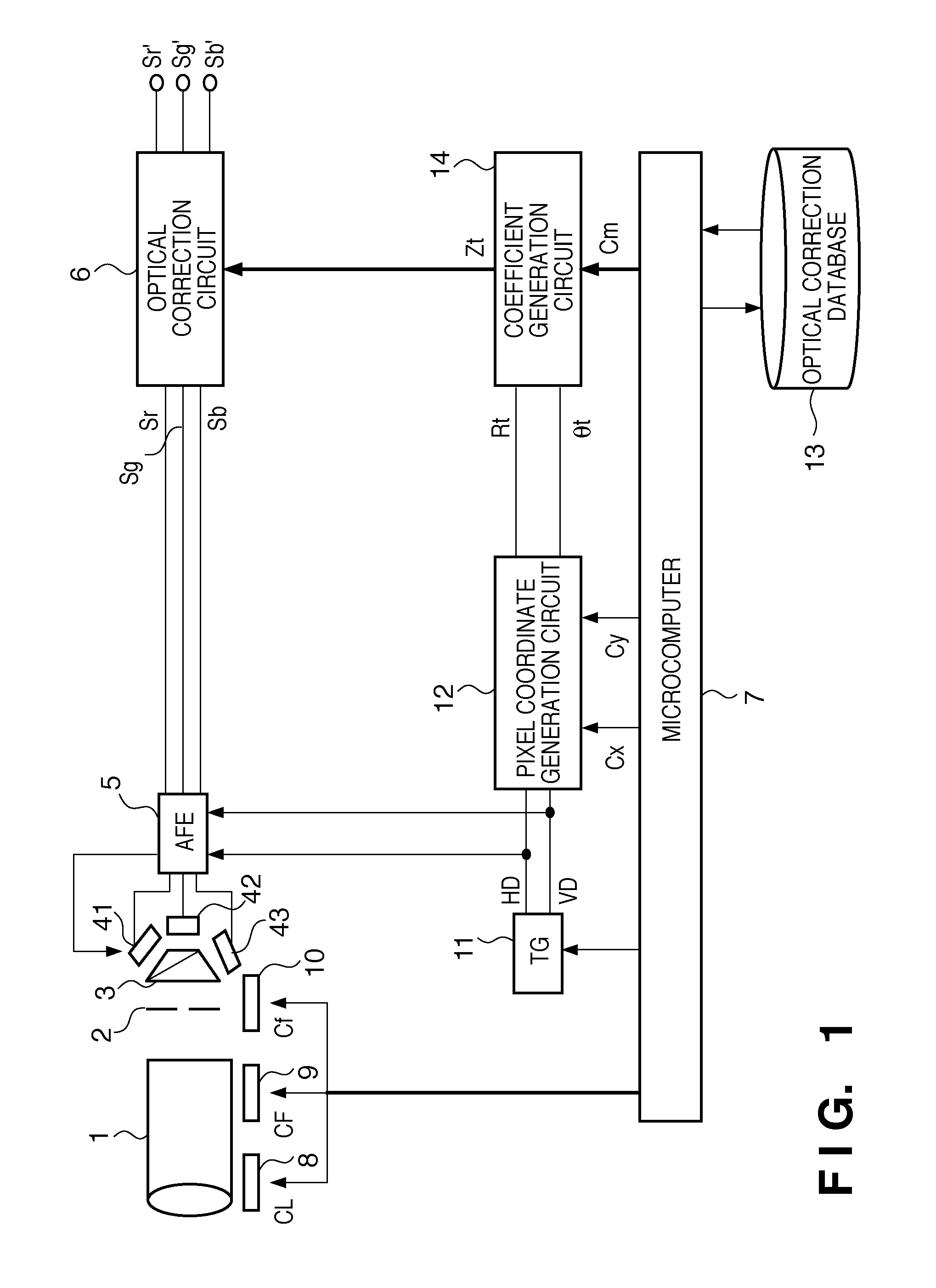
[0037]FIG. 1 is a block diagram showing a schematic configuration of an image sensing apparatus according to Embodiment 1. In FIG. 1, reference numeral 1 denotes a lens unit that includes a zoom lens and a focus lens, and 2 denotes a diaphragm. In the case where the image sensing apparatus is a video camera, an optical system including the lens unit 1 and the diaphragm 2 is controlled according to various factors such as zooming operation, object motion, object change, change in the ambient brightness of the environment, and photographic effects intended by the photographer. In other words, optical parameters, typical examples of which include focal length, focus position and aperture value, are constantly controlled and vary.

[0038]Light that has passed through the optical system including the lens unit 1 and the diaphragm 2 is color-separated by a color separating prism 3 into red (R), green (G) and blue (B), which are then respectively formed on image sensors 41 to 43 as optical i...

embodiment 2

[0088]Embodiment 1 given above described the case of correcting a decrease in the quantity of ambient light as optical characteristics. In Embodiment 2, a case of correcting a magnification chromatic aberration or distortion aberration will be described. The overall configuration of the apparatus is the same as that shown in FIG. 1, and thus a description thereof is omitted here.

[0089]Magnification chromatic aberration correction and distortion aberration correction are processes for repositioning a pixel to a pixel position (coordinates) at which obtained image data at the pixel is to be positioned in the absence of a magnification chromatic aberration or distortion aberration, and not processes for correcting image data itself. Accordingly, in Embodiment 2, the direction and distance of movement of a pixel (coordinates) are stored as correction amount plot data.

[0090]Here, the correction coefficient Zt is the amount of offset in which the amount of offset of the pixel position is ...

embodiment 3

[0101]Next, Embodiment 3 of the present invention will be described. FIG. 14 is a block diagram showing a schematic configuration of an image sensing apparatus according to Embodiment 3. The same components as those of the image sensing apparatus of FIG. 1 are given the same reference numerals, and descriptions thereof are omitted here. The difference from Embodiment 1 of the present invention is that a feature detection circuit 15 that detects features of captured images is disposed prior to the optical correction circuit 6, and that the microcomputer 7 acquires a feature evaluation value Id (feature amount).

[0102]The feature detection circuit 15 carries out at least one of contrast detection, high frequency component detection and motion detection on the digital image signals Sr, Sg and Sb, and outputs a feature evaluation value Id.

[0103]In the case of contrast detection, the feature detection circuit 15 is configured as shown in FIG. 15A, for example. The digital image signals Sr...


PUM


Abstract

In an image sensing apparatus, an image sensing unit generates image data formed via an optical member, a storage unit stores correction information for correcting deterioration of image quality of the image data, a reading unit reads correction information corresponding to a plurality of setting values close to a parameter used to control the optical member from the correction information stored in the storage unit, a conversion unit converts a pixel position of the image data to polar coordinates, a generation unit generates correction information by interpolating the read correction information, and a correction unit corrects the image data at the pixel position at the polar coordinates using the correction information. The storage unit stores correction information corresponding to more polar angles in a range having a greater degree of change in the deterioration of image quality in an angular direction centered on the optical axis of the optical member.

Description

BACKGROUND OF THE INVENTION[0001]1. Field of the Invention[0002]The present invention relates to an image sensing apparatus and an image data correction method, and more particularly to a technique for correcting deterioration of image quality due to optical factors based on optical information.[0003]2. Description of the Related Art[0004]Along with the recent trend toward digital video cameras and digital cameras with an increased number of pixels, high quality images having higher resolution are becoming available. On the other hand, deterioration of images due to pixel size reduction, and deterioration of image quality that is principally caused by the optical system, such as reduction in the quantity of light in the periphery of an image circle, magnification chromatic aberrations and distortion aberrations, due to factors such as difficulty in designing small lenses, are becoming more noticeable.[0005]Deterioration of image quality due to optical factors as described above is c...

Claims


Application Information

Patent Timeline
Patent Type & Authority Patents(United States)
IPC IPC(8): H04N5/225
CPCH04N5/3572H04N25/61
Inventor TERASAWA, KEN
Owner CANON KK
Why Eureka
Try Eureka