Emulation of power shutoff behavior for integrated circuits

a technology of integrated circuits and shutoff behaviors, applied in the direction of electrical/magnetic computing, analogue processes for specific applications, instruments, etc., can solve the problems of not meeting the challenges of conventional emulation systems, unable to capture the intended behavior in the design rtl, and impossible to achieve the effects of software simulators

Active Publication Date: 2013-01-08
CADENCE DESIGN SYST INC
View PDF17 Cites 30 Cited by
  • Summary
  • Abstract
  • Description
  • Claims
  • Application Information

AI Technical Summary

Benefits of technology

[0016]According to another aspect, determining the emulation module may include: using a randomizing value to select a power-switch hardware element that provides values for a sequential element output when using the emulation module. According to another aspect, determining the emulation module may include: selecting a multiplexer that receives a randomizing input and provides values for a sequential element in a power loss state when using the emulation module. According to another aspect, determining the emulation module may include: selecting a control element that receives power-switch signals for the power domains and adjusts values for a sequential element in a power loss state when using the emulation module.
[0017]According to another aspect, the method may further include: saving one or more values for the simulated power levels of the IC. According to another aspect, the method may further include: saving into a database selected values for IC primary inputs, IC primary outputs and sequential element outputs from using the emulation module; and using at least some values from the database to calculate power-management characteristics for a selected power domain. According to another aspect, the method may further include: associating emulation-module values with the power domains; calculating power-mode values for the simulated changing power levels of the IC from the emulation-values; and displaying the power mode values for the IC.
[0018]Additional embodiments relate to an apparatus for carrying out any one of the above-described methods, where the apparatus includes a computer for executing instructions related to the method. For example, the computer may include a processor with memory for executing at least some of the instructions. Additionally or alternatively the computer may include circuitry or other specialized hardware for executing at least some of the instructions. Additional embodiments also relate to a computer-readable medium that stores (e.g., tangibly embodies) a computer program for carrying out any one of the above-described methods with a computer. In these ways the present invention enables improved emulation systems for verifying power shutoff behavior of IC designs

Problems solved by technology

In fact, emulators can operate at speed fast enough to allow the intended application software to run on the prototype system, which is something the software simulator can never accomplish.
Low-power designs for ICs (e.g., for applications in wireless and portable electronics) have led to additional challenges for design verification including minimizing leakage power dissipation, designing efficient packaging and cooling systems for high-power integrated circuits, and verifying functionalities of low-power or no power situations early in the design.
These power management issues have become even more critical in view of the continuous shrinking of device dimensions with the next generation of semiconductor processing technology.
However, conventional emulation systems have not responded to these challenges.
These power management design techniques may significantly change the design intent, yet none of the intended behavior can be captured in the RTL of the design.
This deficiency creates a gap in the RTL to Graphic Data System II (GDSII) implementation and verification flow where the original RTL can no longer be relied upon as a correct representation of the design, and thus cannot be used to verify the final netlist implementation containing power management implementations.
However, conventional emulation systems have not incorporated these aspects so as to enable hardware-based verification of critical power management functions such as power shutoff, cell isolation and state retention in a low power design.

Method used


Image

  • Emulation of power shutoff behavior for integrated circuits
  • Emulation of power shutoff behavior for integrated circuits
  • Emulation of power shutoff behavior for integrated circuits

Examples


Embodiment Construction

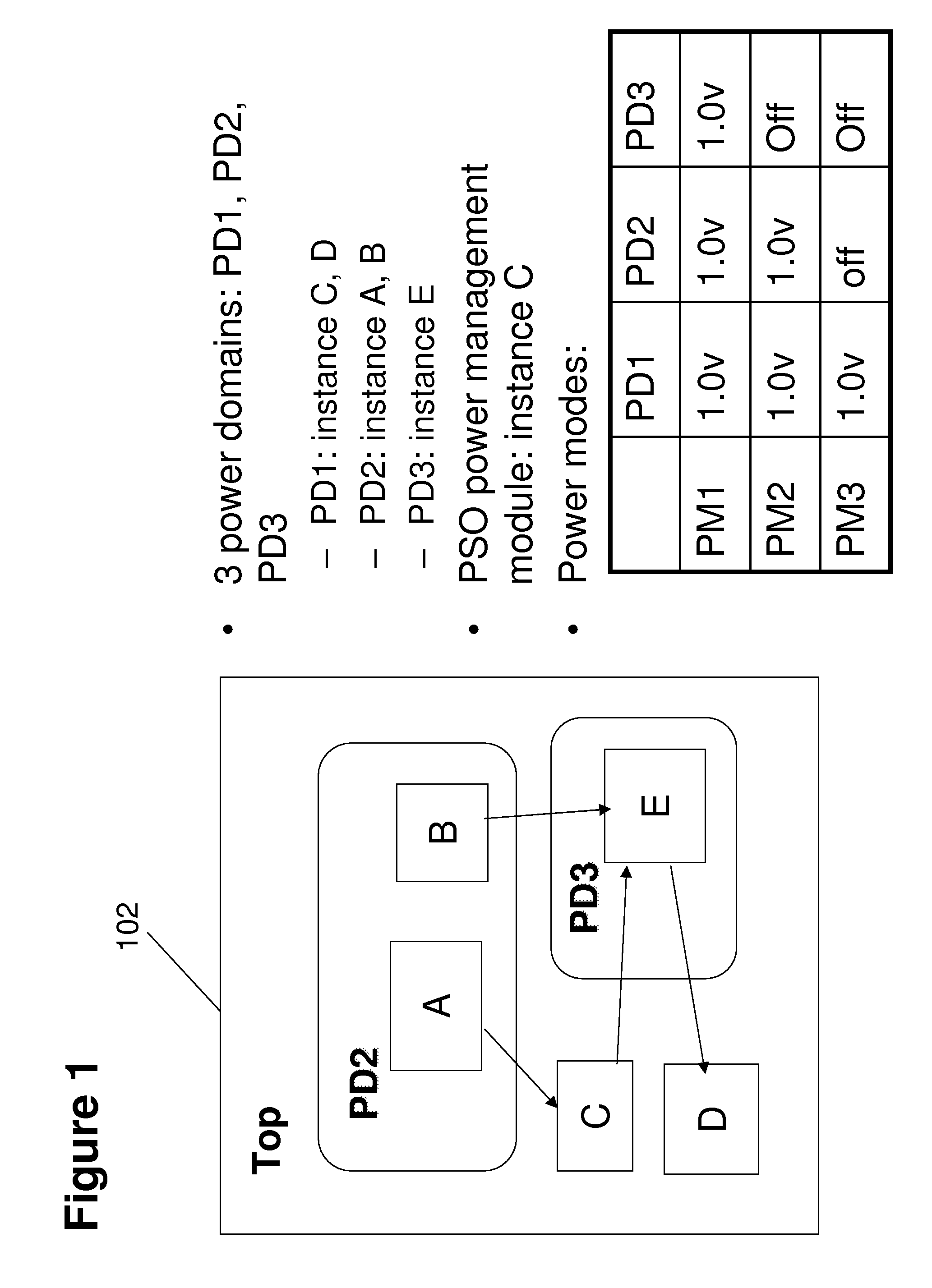
[0029]FIG. 1 shows an exemplary low-power design 102 for an IC in an embodiment of the present invention. The power design 102 includes a top cell instance “Top”, which has sub-instances A, B, C, D and E. A corresponding CPF (Common Power Format) file indicates there are three power domains: PD1, PD2 and PD3. The instance C and D are in power domain PD1; instance A, B are in power domain PD2; instance E is in power domain PD3. Power management with power shutoff (PSO) is controlled by a power management module in instance C. There are three valid power modes: power mode PM1, PM2 and PM3. In power mode PM1, all three power domains are powered on, in power mode PM2 only power domain PD3 is off, and in power mode PM3 only power domain PD1 is powered on. Functional verification by an emulation system is directed towards verifying the design's PSO behavior in transitions between the power modes. As discussed below in greater detail, relevant PSO features include correct power modes, powe...


PUM


Abstract

A method for modeling power management in an integrated circuit (IC) includes: specifying a circuit design and a power architecture for the IC, the power architecture including a plurality of power domains for specifying power levels in different portions of the IC; determining an emulation module for the IC by including one or more hardware elements for modeling the power architecture in the emulation module; and using the emulation module to simulate changing power levels in one or more power domains of the IC including a power shutoff in at least one power domain.

Description

CROSS-REFERENCE TO RELATED APPLICATIONS[0001]This application claims the benefit of U.S. Provisional Application No. 60 / 984,178, filed Oct. 31, 2007, and incorporated herein by reference in its entirety.BACKGROUND OF THE INVENTION[0002]1. Field of Invention[0003]The present invention relates generally to design verification systems for integrated circuits (ICs) and more particularly to the use of hardware-based functional verification systems for verifying power shutoff behavior of IC designs.[0004]2. Description of Related Art[0005]The development of EDA (electronic design automation) tools has included a number of hardware-based functional verification systems including logic emulation systems and simulation accelerators. For simplicity these tools will be referred to collectively as emulation systems in the subsequent discussion.[0006]Emulation systems can be used to verify the functionalities of electronic circuit designs prior to fabrication as chips or as electronic systems. T...

Claims


Application Information

Patent Timeline
Patent Type & Authority Patents(United States)
IPC IPC(8): G06G7/54G06F9/455G06F17/50
CPCG06F17/5036G06F17/5022G06F2217/78G06F30/33G06F2119/06G06F30/367
Inventor LIN, TSAIR-CHINZHU, BINGBELETSKY, PLATON
Owner CADENCE DESIGN SYST INC
Why Eureka
Try Eureka