Perfused core dielectrically loaded dipole microwave antenna probe

a dielectric load and microwave antenna technology, applied in waveguide devices, resonant antennas, therapy, etc., can solve the problems of reducing the strength of the probe, putting undue stress on the probe, and so as to improve the power delivery performance and power handling. , the effect of reducing the temperature of the componen

Active Publication Date: 2013-01-15
TYCO HEALTHCARE GRP LP
View PDF162 Cites 33 Cited by
  • Summary
  • Abstract
  • Description
  • Claims
  • Application Information

AI Technical Summary

Benefits of technology

[0009]The present disclosure provides a high-strength electromagnetic surgical ablation probe that includes a cooled and dielectrically buffered antenna assembly. A cable provides electromagnetic energy to the probe via a coaxial conductor and / or provides coolant via a fluid conduit to improve power delivery performance and power handling, and to reduce component temperatures. Suitable coolants include deionized water, sterile water, or saline.
[0011]A feed point seal joins a distal end of the hypotube to a porous core enclosed within the probe distal radiating section. The feed point seal includes one or more an openings defined therethrough to provide a fluid path between the fluid channels and the porous core. The feed point seal includes an opening, which may be axially positioned, to enable the inner conductor to pass therethough, e.g., to extend distally into the porous core. The feed point seal additionally or alternative seals one or more conductors of the feedline, which may help prevent coaxial feedline short circuiting (e.g., shorts between conductors and / or other elements of the probe).
[0012]A microwave ablation antenna in accordance with the present disclosure may be configured to operate in a range of about 915 MHz to about 2.45 GHz, or within any other suitable frequency range. In one embodiment, the hypotube ribs press into the coaxial cable thereby forming a separate fluid inflow channel and fluid outflow channel. A coolant, such as saline or dionized water, is introduced into a proximal end of the inflow channel, from where it flows distally, through openings in the feed point seal into a radiating section that includes a radiating section having a porous core. The porous core is perfused with coolant, which may help to reduce probe temperatures, and may provide improved dielectric coupling between the probe and tissue. The dual-chamber design of the disclosed probe may provide better coolant dispersion within the probe, thereby providing increased coolant efficiency, and allowing the size of the probe to be greatly reduced.
[0013]The porous perfused core may include a separator to define a two chamber perfusion arrangement wherein coolant would first travel distally past the distal radiating section through an inflow chamber region, then return proximally through an outflow chamber region. The porous core may be formed from porous ceramic, porous metal, or any suitable material that permits coolant fluid to circulate. Additionally, the porous core may add strength to the dielectric surface of the probe.

Problems solved by technology

However, at slightly elevated temperatures above the approximate range of 43° C. to 45° C., thermal damage to most types of normal cells is routinely observed.
However, providing coolant passages within a probe may reduce probe strength, because such passages necessitate the introduction of voids into the probe structure.
During such a procedure, negotiating the probe through, for example, fibrous thoracic tissue and ribs may place undue stresses on the probe.
Additionally, a cooled probe may lack sufficient strength to withstand the stresses imposed by such percutaneous insertions, which may result in probe failure.

Method used


Image

  • Perfused core dielectrically loaded dipole microwave antenna probe
  • Perfused core dielectrically loaded dipole microwave antenna probe
  • Perfused core dielectrically loaded dipole microwave antenna probe

Examples


Embodiment Construction

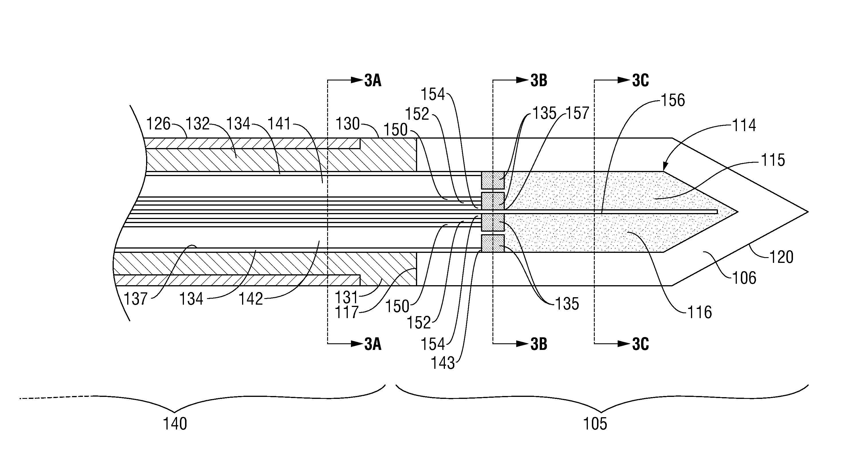
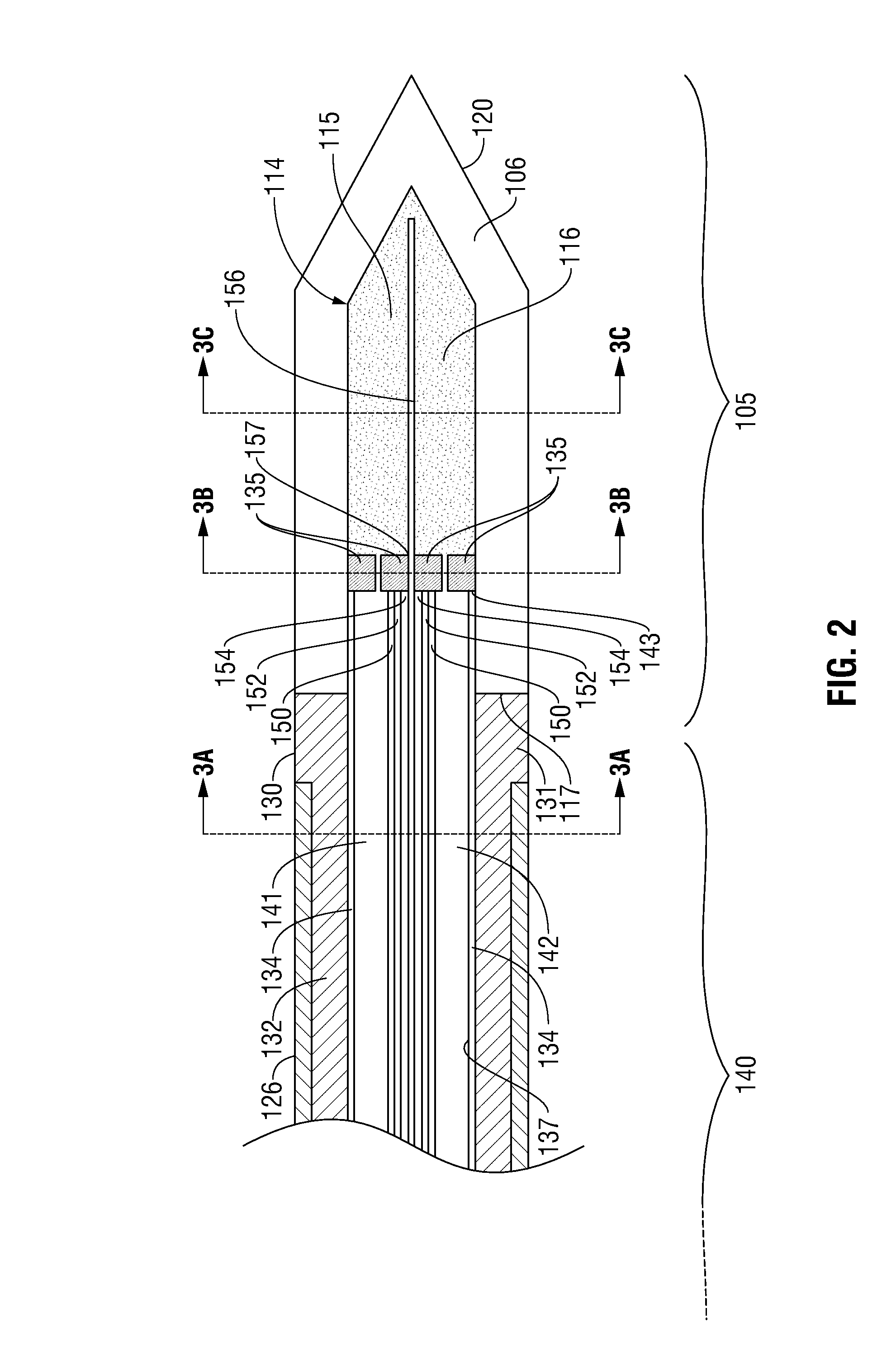
[0026]Particular embodiments of the present disclosure will be described hereinbelow with reference to the accompanying drawings; however, it is to be understood that the disclosed embodiments are merely exemplary of the disclosure, which may be embodied in various forms. Well-known functions or constructions are not described in detail to avoid obscuring the present disclosure in unnecessary detail. Therefore, specific structural and functional details disclosed herein are not to be interpreted as limiting, but merely as a basis for the claims and as a representative basis for teaching one skilled in the art to variously employ the present disclosure in virtually any appropriately detailed structure.

[0027]In the drawings and in the descriptions that follow, the term “proximal,” as is traditional, shall refer to the end of the instrument that is closer to the user, while the term “distal” shall refer to the end that is farther from the user.

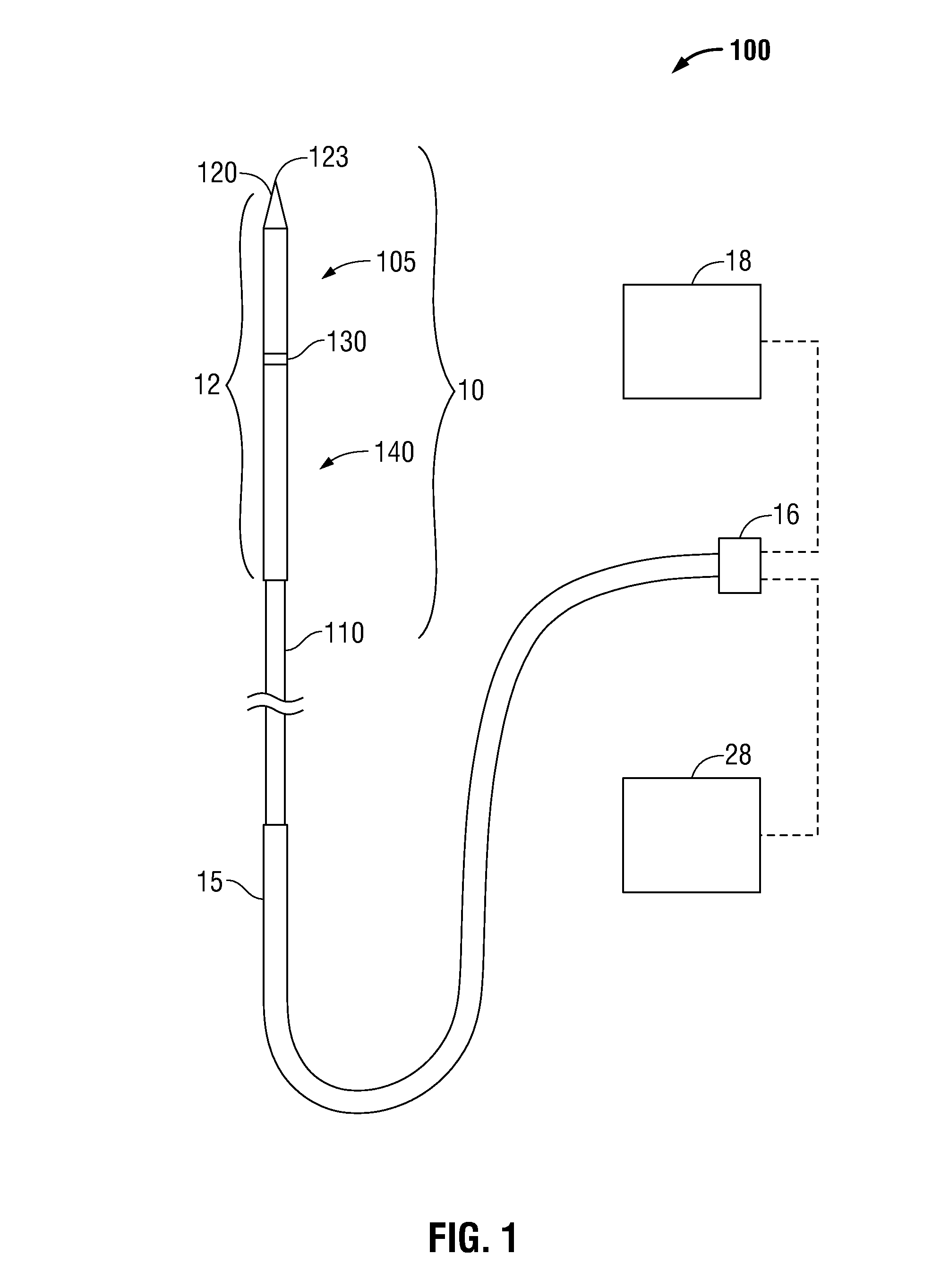
[0028]FIG. 1 shows an embodiment of a micr...


PUM

PropertyMeasurementUnit
threshold temperatureaaaaaaaaaa
temperaturesaaaaaaaaaa
frequencyaaaaaaaaaa

Abstract

A microwave surgical ablation probe having an arrangement of coolant channels in fluid communication with a cooling chamber disposed within the distal end of the probe is disclosed. A hypotube having one or more longitudinal ribs extending radially inward from an inner surface thereof is coaxially disposed around a coaxial feedline. The longitudinal ribs of the hypotube engage an outer sheath of the feedline to define a fluid inflow channel to deliver coolant to the cooling chamber, and a fluid outflow channel to receive fluid from the cooling chamber. The cooling chamber may be formed from porous ceramic or porous metallic material that provides structural support to the probe while permitting coolant to circulate therethrough. The probe includes dielectric and choke members that are adapted to control the microwave radiation pattern (e.g., ablation shape), and which may provide improved coupling of the probe to tissue.

Description

BACKGROUND[0001]1. Technical Field[0002]The present disclosure relates to systems and methods for providing energy to biological tissue and, more particularly, to a microwave ablation surgical probe having a porous core through which coolant is circulated and methods of use and manufacture therefor.[0003]2. Background of Related Art[0004]Energy-based tissue treatment is well known in the art. Various types of energy (e.g., electrical, ultrasonic, microwave, cryogenic, thermal, laser, etc.) are applied to tissue to achieve a desired result. Microwave energy can be delivered to tissue using an antenna probe. Presently, there are several types of microwave probes in use, e.g., monopole, dipole, and helical. One type is a monopole antenna probe, which consists of a single, elongated microwave conductor exposed at the end of the probe. The probe is typically surrounded by a dielectric sleeve. The second type of microwave probe commonly used is a dipole antenna, which consists of a coaxia...

Claims


Application Information

Patent Timeline
Patent Type & Authority Patents(United States)
IPC IPC(8): A61B18/18
CPCA61B18/1815H01Q9/30A61B18/18A61B2018/00023Y10T29/49016A61B2018/1869
Inventor BONN, KENLYN S.SMITH, IAN S.
Owner TYCO HEALTHCARE GRP LP
Why Eureka
Try Eureka