Mixed cesium sodium and lithium halide scintillator compositions

a technology of lithium halide and mixture, which is applied in the field of scintillator compositions, can solve the problems that the actual use of scintillator spectrometers and various practical applications has been difficult to predict, and the requirements on the whole cannot be met by many of the commercially available scintillator compositions, and achieves high gamma-ray and neutron stopping efficiency, robust light output, and fast response

Active Publication Date: 2013-01-29
RADIATION MONITORING DEVICES
View PDF18 Cites 12 Cited by
  • Summary
  • Abstract
  • Description
  • Claims
  • Application Information

AI Technical Summary

Benefits of technology

[0033]Scintillator compositions can include a single quaternary compound selected from those described herein or a mixture of different compounds described herein. Compositions can, e.g., include mixed scintillator compositions with at least two different CsXLa halide compounds, where X is Na or Li. Thus, mixed scintillator compositions can include a mixture of at least two quaternary compounds having Na or Li at the second position, such that the quaternary compound mixture includes, for example, Cs(Na,Li)La halide. Halides can include, for example, F, Cl, Br, or I. Certain embodiments can further include mixed scintillator compositions that include a mixture of at least two quaternary compounds having Na or Li at the second position and at least two different halides at the fourth position, such that the quaternary compound mixture includes, for example, Cs(Na,Li)La(Cl,Br) or any other possible combination of halides and Na and Li. Thus, as different compounds may have different scintillation characteristics, one advantage of the present invention includes the ability to select or customize a particular mixed composition ratio or formulation, where a particular selection or formulation is at least partially based on intended use of the scintillator composition and / or desired properties or scintillation / performance characteristics. For example, a particular mixed quaternary compound composition (e.g., mixed CsXLa halide composition such that X is Na or Li) formulation may be selected based on one or more of a variety of factors, such as desired stopping power (e.g., at least partially as a function of atomic number), neutron response, bandgap levels tuning / optimization for Ce emission and light output, pulse shape discrimination, gamma-ray sensitivity, and the like.
[0034]The scintillator compositions of the invention are particularly useful, for example, for spectroscopy detection of energetic photons (e.g., X-rays, gamma-rays), as well as for neutron emission detection. Notable characteristics for the scintillation compositions of the invention include surprisingly robust light output, high gamma-ray and neutron stopping efficiency (attenuation), fast response, and good non-proportionality. Furthermore, the scintillator compositions can be efficiently and economically produced. Thus, detectors having scintillator compositions described in the present invention are useful in a wide variety of applications, including without limitation nuclear and high energy physics research, medical imaging, diffraction, non-destructive testing, nuclear treaty verification and safeguards, and geological exploration.
[0035]The scintillator composition of the present invention can optionally include a “dopant”. Dopants can affect certain properties, such as physical properties (e.g., brittleness, etc.) as well as scintillation properties (e.g., luminescence, etc.) of the scintillator composition. The dopant can include, for example, cerium (Ce), praseodymium (Pr), lutetium (Lu), lanthanum (La), europium (Eu), samarium (Sm), strontium (Sr), thallium (Tl), chlorine (Cl), fluorine (F), iodine (I), and mixtures of any of the dopants. The amount of dopant present will depend on various factors, such as the application for which the scintillator composition is being used; the desired scintillation properties (e.g., emission properties, timing resolution, etc.); and the type of detection device into which the scintillator is being incorporated. For example, the dopant is typically employed at a level in the range of about 0.1% to about 20%, by molar weight. In certain embodiments, the amount of dopant is in the range of about 0.1% to about 100%, or about 0.1% to about 5.0%, or about 5.0% to about 20%, by molar weight.
[0036]The scintillator compositions of the invention may be prepared in several different forms. In some embodiments, the composition is in a crystalline form (e.g., monocrystalline). Scintillation crystals, such as monocrystalline scintillators, have a greater tendency for transparency than other forms. Scintillators in crystalline form (e.g., scintillation crystals) are often useful for high-energy radiation detectors, e.g., those used for gamma-ray or X-ray detection. However, the composition can include other forms as well, and the selected form may depend, in part, on the intended end use of the scintillator. For example, a scintillator can be in a powder form. It can also be prepared in the form of a ceramic or polycrystalline ceramic. Other forms of scintillation compositions will be recognized and can include, for example, glasses, deposits, vapor deposited films, microcolumnar, or other forms suitable for radiation detection as described herein. It should also be understood that a scintillator composition might contain small amounts of impurities. Also, minor amounts of other materials may be purposefully included in the scintillator compositions to affect the properties of the scintillator compositions.
[0037]Methods for making crystal materials can include those methods described herein and may further include other techniques. Typically, the appropriate reactants are melted at a temperature sufficient to form a congruent, molten composition. The melting temperature will depend on the identity of the reactants themselves (see, e.g., melting points of reactants), but is usually in the range of about 300° C. to about 1350° C. Non-limiting examples of the crystal-growing methods can include certain techniques of the Bridgman-Stockbarger methods; the Czochralski methods, the zone-melting methods (or “floating zone” method), the vertical gradient freeze (VGF) methods, and the temperature gradient methods. See, e.g.,

Problems solved by technology

These requirements on the whole cannot be met by many of the commercially available scintillator compositions.
While general classes of chemical compositions may be identified as potentially having some attractive scintillation characteristic(s), specific compositions / formulations having both scintillation characteristics and physical properties necessary for actual use in scintillation spectrometers and various practical applications have proven difficult to predict.
Specific scintillation properties are not necessarily predictable from chemical composition alone, and preparing effective scintillator compositions from even candidate materials often proves difficult.
With the advent of X-ray CT in the 1970's, a major commercial field emerged as did a need for different scintillator compositions, as NaI(Tl) was not able to meet the requirements of CT imaging.
As the methodology of scintillator development evolved, new materials have been added, and yet, specific applications are still hampered by the lack of scintillators suitable for particular applications.
While it may be possible to reject a potential scintillator for a specific application based solely on composition, it is typically difficult to predict whether even a material with a promising composition can be used to produce a useful scintillator with the desired properties.
An important challenge in homeland security monitoring is not only to detect hidden radioactive materials but also to distinguish them from routinely used radiopharmaceuticals as well as from naturally occurring benign radioactive materials.
Existing scintillator materials and commercial radiation detectors do not meet the current needs for radiation monitoring and weapons detection.
For example, existing scintillator compositions and detectors typically lack the one or more important scintillation properties (e.g., high energy resolution, light output, stopping power, fast response, and the like) that are desired and / or are not useful in detecting both energetic photons (e.g., gamma-rays and X-rays) as well as neutron emission.

Method used


Image

  • Mixed cesium sodium and lithium halide scintillator compositions
  • Mixed cesium sodium and lithium halide scintillator compositions
  • Mixed cesium sodium and lithium halide scintillator compositions

Examples


example 1

[0051]The present example provides a method for growing and provides characterization for the scintillator composition crystals. The following examples are offered by way of illustration, not by way of limitation.

Crystal Growth of Compounds Exemplified with Cs2NaLaBr6, Cs2NaGdI6, Cs2NaLaI6, and Cs2NaLuI6

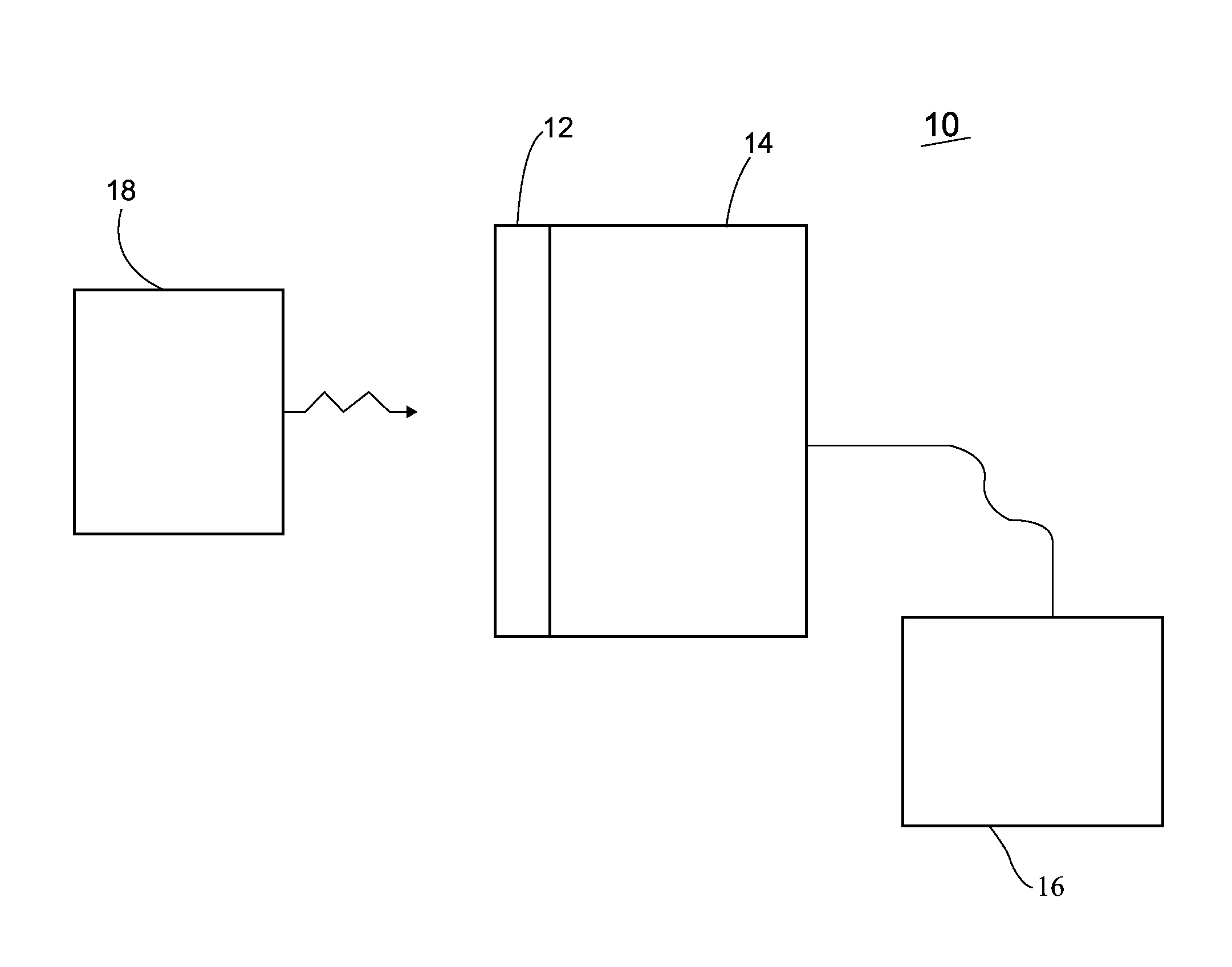
[0052]In one example, a one zone Bridgman furnace was used for crystal growth. Typical growth rates for the Bridgman process are about 1-6 mm / hour. Growth rates ranging from about 1 mm / day to about 1 cm / hour may be utilized. The range of rates may be extended to improve material quality.

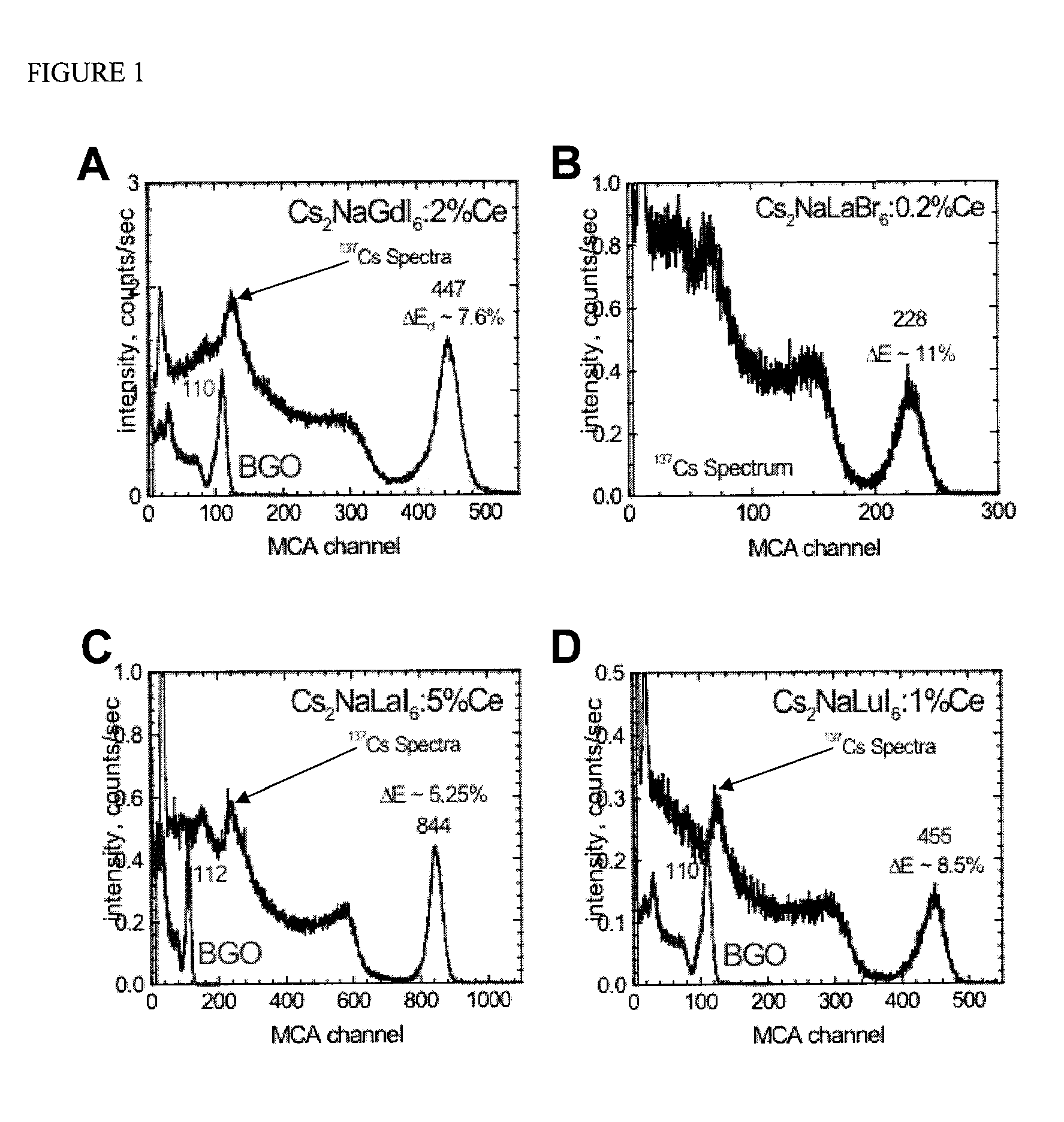
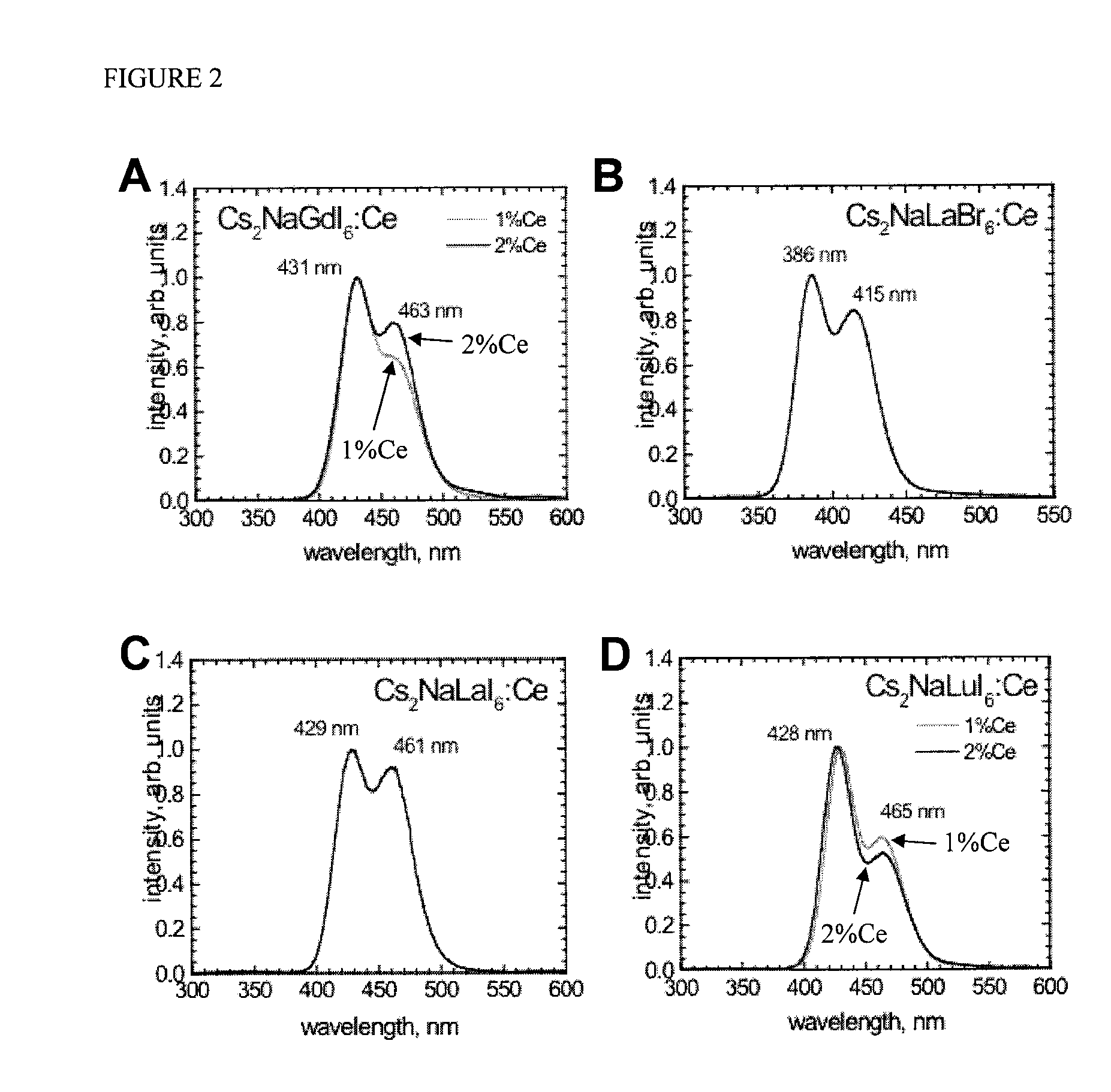
[0053]Cs2NaLaBr6, Cs2NaGdI6, Cs2NaLaI6, and Cs2NaLuI6 have a cubic crystal structure. The densities of Cs2NaLaBr6, Cs2NaGdI6, Cs2NaLaI6, and Cs2NaLuI6 are between about 3.9 and about 4.6 g / cm3. The compositions melt congruently at approximately 78, 925, 778, and 1050° C., respectively, and therefore their crystals can be grown using melt based methods such as those described by Bridgman and Czochrals...


PUM


Abstract

The present invention relates to scintillator compositions and related devices and methods. The scintillator may include, for example, a mixed scintillator composition including at least two different CsXLa halide compounds and a dopant, wherein X is Na or Li. Related radiation detection devices and methods are further included.

Description

CROSS REFERENCES TO RELATED APPLICATIONS[0001]The present application is a continuation of U.S. application Ser. No. 12 / 405,168, now U.S. Pat. No. 7,977,645, entitled “Mixed Cesium Sodium and Lithium Halide Scintillator Compositions,” filed on Mar. 16, 2007 which is a continuation-in-part of U.S. application Ser. No. 11 / 938,176, now U.S. Pat. No. 7,655,919, entitled “Cesium and Lithium-Containing Quaternary Compound Scintillators,” filed on Nov. 9, 2007, and is a continuation-in-part of U.S. application Ser. No. 11 / 938,182, entitled “Cesium and Sodium-Containing Quaternary Compound Scintillators,” filed on Nov. 9, 2007, and claims the benefit under 35 U.S.C. 119(e) of U.S. Application No. 61 / 045,891, filed on Apr. 17, 2008.BACKGROUND OF THE INVENTION[0002]The present invention relates to scintillator compositions and related devices and methods. More specifically, the present invention relates to scintillator compositions including a scintillation compound and a dopant for use, for ...

Claims


Application Information

Patent Timeline
Patent Type & Authority Patents(United States)
IPC IPC(8): G01T1/20
CPCG01T1/202
Inventor SHAH, KANAI S.HIGGINS, WILLIAM M.VAN LOEF, EDGAR V.GLODO, JAROSLAW
Owner RADIATION MONITORING DEVICES
Why Eureka
Try Eureka