Energy supply for a blade adjustment device pertaining to a wind energy installation

a technology of energy supply and adjustment device, which is applied in the direction of emergency power supply arrangement, electric generator control, machines/engines, etc., can solve the problems of limited achieve the effect of increasing the voltage in the emergency circuit, dissipating excessive electric power, and improving system characteristics

Active Publication Date: 2013-03-26
SIEMENS GAMESA RENEWABLE ENERGY SERVICE GMBH
View PDF37 Cites 8 Cited by
  • Summary
  • Abstract
  • Description
  • Claims
  • Application Information

AI Technical Summary

Benefits of technology

[0009]Another advantage of the invention is that said advantages relating to the conservation of the electric energy store and to the improvement of the system characteristic can be achieved with little outlay in terms of hardware.
[0010]The power flow can be determined simply by the protection device determining the voltage in the emergency circuit and limiting its increase during emergency operation. Here, the invention takes advantage of the basically simple connection that a generator-type operation of the servomotor increases its terminal voltage, and thus the voltage in the entire emergency circuit increases. As opposed to normal operation, where the voltage in the emergency circuit is at most as high as the rated voltage of the electric energy store of the emergency circuit, in the case of the emergency operation and power flow out of the servomotor, the voltage increases to above the rated voltage of the electric energy store. Such a voltage change can be detected by means of the power flow detector module and thus the power flow direction can be determined. It cooperates with the discharge module such that, in the case of a power flow out of the servomotor, the voltage in the emergency circuit is limited, to be precise preferably to a value which is acceptable for the electric energy store. The damaging high-current charge of the energy store, which otherwise results from the increase in voltage, can in this way be reliably avoided. Expediently, the protection device is configured such that, during emergency operation, the voltage in the emergency circuit is limited to a value which is slightly above the rated voltage of the electric energy store, to be precise preferably approximately 5 to 20% above the rated voltage.
[0011]It is not, however, absolutely necessary for the power limitation by way of the discharge module to take place only via the voltage. Alternatively, or additionally, provision may be made to limit the current flow in the emergency circuit. This is of particular advantage in a low-impedance electric energy store in which high-current charging can take place already in the case of slight or hardly measurable changes in voltage. Depending on the technology used for the electric energy store, it can also be expedient to use a combination of the parameters voltage and current for the power flow detector module, in particular as a signed product of voltage and power.
[0012]In order to dissipate the excessive electric power generated by the servomotor during shift operation, the discharge module expediently has a brake chopper with a brake resistor. A brake chopper is understood to mean a combination of a synchronized switch (chopper) with an ohmic resistor as energy converter (from electric into thermal energy). Changing the duty factor when controlling the synchronized switch can determine how much electric power is converted via the discharge module into thermal energy and is thus removed from the emergency circuit. A brake chopper of this type thus enables a sensitive change in the power flow in the emergency circuit with little complexity in terms of hardware.
[0013]Preferably, the brake chopper is designed as a brake chopper of a converter and, during emergency operation, is connected via a switching element to the emergency circuit. The invention here takes advantage of the fact that converters typically already have a brake chopper in order to be able to dissipate any excessive energy. By using this brake chopper, which is present in most cases in any case, as the brake resistor for the emergency circuit, hardly any additional hardware is, in this respect, necessary for realizing the invention. Often, the converter provided in the pitch circuit is designed such that it has an intermediate circuit. In such a case, the brake chopper can be advantageously connected to the intermediate circuit. However, provision may also be made for the brake chopper to be connected to an inverter or an H-bridge circuit. Even though the arrangement of the brake chopper on the converter represents the most common embodiment, the invention can also be used in designs in which the brake chopper is connected to the inverter of the converter or of a downstream H-bridge circuit for controlling a DC motor.
[0014]According to a particularly preferred aspect of the invention, the discharge module has a setpoint value change module for the intermediate circuit. Said module is designed for changing a setpoint value for the energy state of the intermediate circuit, to be precise in the case of emergency operation with actuation of the servomotor via the emergency circuit. In the case of a DC voltage intermediate circuit, the setpoint value is a voltage, and the threshold value change module is designed to specify a lower voltage value as the setpoint value during emergency operation. It is then expedient to lower the setpoint voltage of the intermediate circuit to a voltage approximately equal to the rated voltage of the electric energy store. A threshold value of about 5 to 20% above the rated voltage of the electric energy store is preferred. This achieves a quick reaction of the brake resistor, to be precise in particular in those cases where the chopper, which is present in any case, of the converter acts as brake resistor. (This applies accordingly to currents in a DC intermediate circuit.)

Problems solved by technology

Furthermore, any possible increase in voltage in the emergency circuit is limited, so that no damaging values can be reached.

Method used


Image

  • Energy supply for a blade adjustment device pertaining to a wind energy installation
  • Energy supply for a blade adjustment device pertaining to a wind energy installation
  • Energy supply for a blade adjustment device pertaining to a wind energy installation

Examples


Embodiment Construction

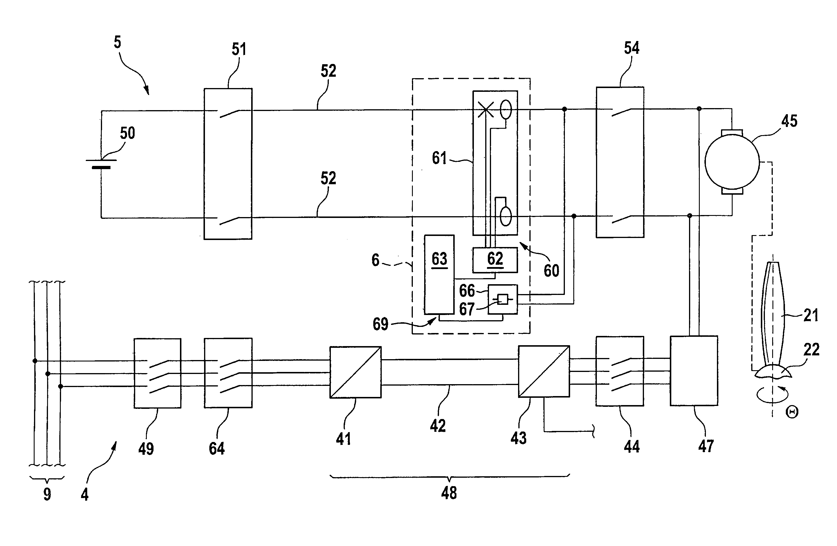
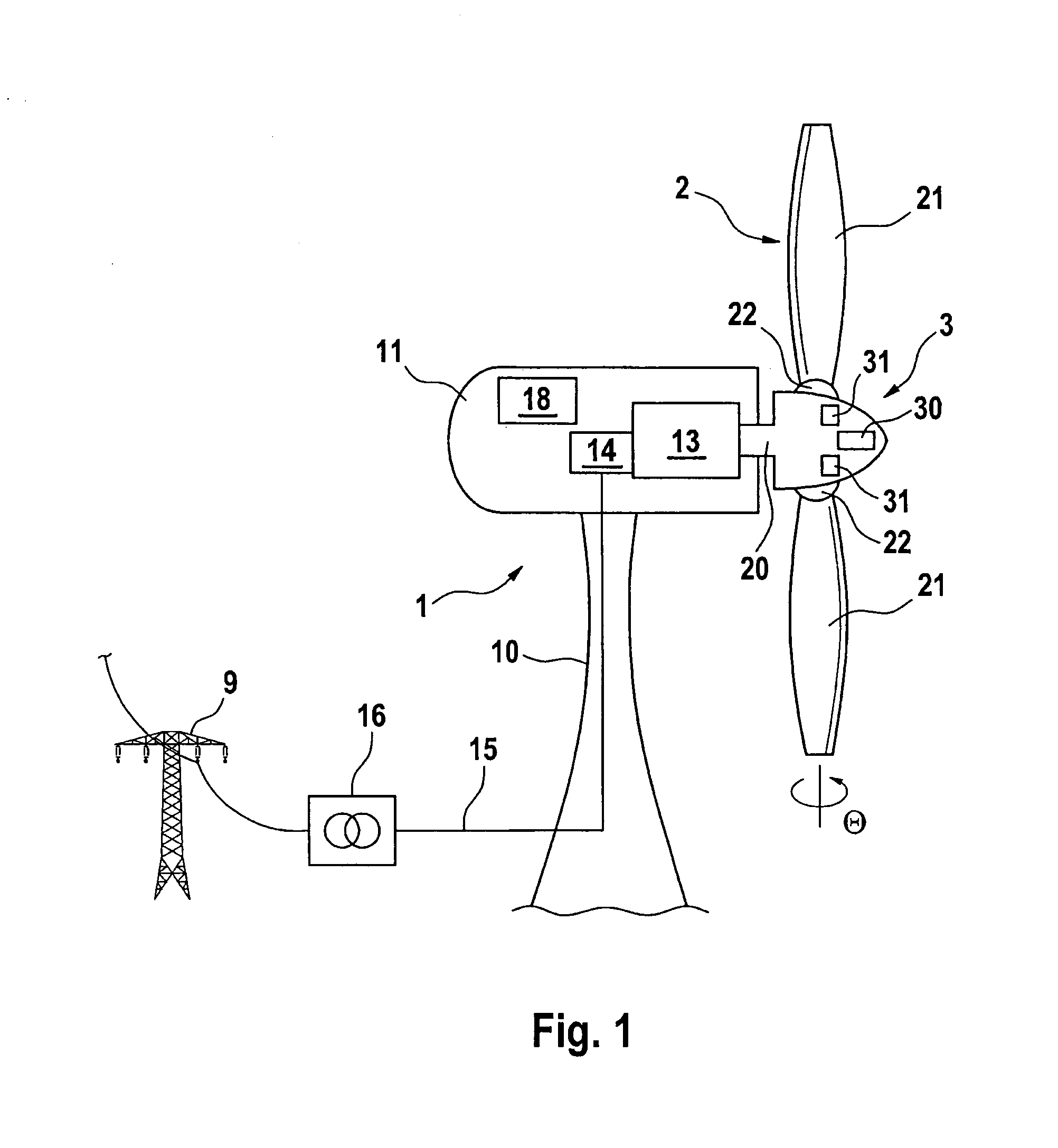
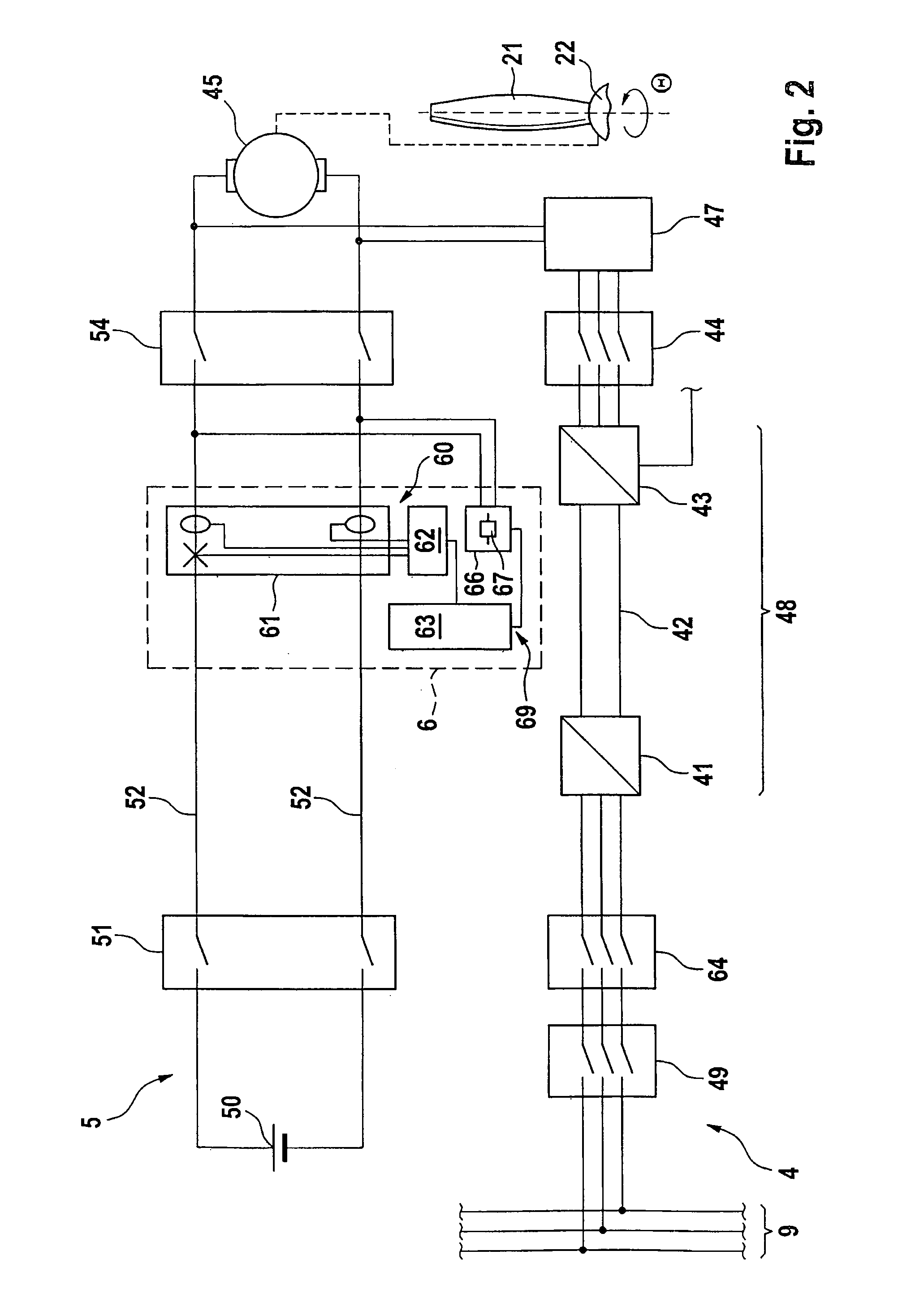
[0024]A wind installation denoted as a whole by the reference numeral 1 comprises a tower 10 with a pod 11 which is arranged at its uppermost end in an azimuth plane such that it can move rotationally. On one front end of the pod 11, a rotor 2 is arranged rotatably via a rotor shaft 20. The rotor 2 comprises a plurality of (two in the illustrated example) rotor blades 21. A rotor blade hub 22 connects the propeller blades 21 to the rotor shaft 20. The rotor shaft 20 drives a generator 14 arranged in the pod 11 in order to generate electric energy. The electric energy is guided to a converter 14 and output to an electric supply system 9 via a three-phase line (only one phase is illustrated) 15 and a transformer 16. Furthermore, a control device 18 for the wind energy installation 1 is also arranged in the pod 11. Said control device serves in a manner known per se for the operational control of the wind energy installation.

[0025]The rotor blades 21 are arranged on the hub 22 such tha...


PUM


Abstract

A wind energy installation includes a tower provided with rotor blades that are adjusted using a servomotor connected to a pitch circuit and an emergency circuit. During normal operation the rotor blades are actuated by the pitch circuit and during emergency operation are actuated by the emergency circuit. The emergency circuit has an electric energy store, a switching device, connection lines to the servomotor and a protection device which includes comprises a power flow detector module (60) designed for determining whether electric power flows into or from the servomotor and a discharge module designed to limit the voltage and / or current in the emergency circuit in the case of a power flow from the servomotor.

Description

REFERENCE TO RELATED APPLICATIONS[0001]This application is a national stage application under 35 USC 371 of International Application No. PCT / EP2007 / 001594, filed Feb. 23, 2007, which claims the priority of German Patent Application No. 10 2006 009 127.2, filed Feb. 24, 2006, the contents of both of which prior applications are incorporated herein by reference.FIELD OF THE INVENTION[0002]The invention relates to an energy supply for blade adjustment devices pertaining to a wind energy installation in general, and in particular to a wind energy installation having a rotor with adjustable rotor blades, wherein a servomotor connected to a pitch circuit and an emergency circuit is provided for adjusting the rotor blades.BACKGROUND OF THE INVENTION[0003]Wind energy installations with pitch-adjustable rotor blades generally have, for reasons of operational reliability, an emergency drive device with an autarkic energy store, such as a rechargeable battery. This emergency drive device with...

Claims


Application Information

Patent Timeline
Patent Type & Authority Patents(United States)
IPC IPC(8): F03D9/00H02P9/04B64C11/00
CPCF03D7/0224F05B2260/76F05B2270/1074H02H3/18Y02B10/72Y02E10/721Y02E10/723Y02E10/766H02J9/06Y02B10/70Y02E10/76Y02E10/72
Inventor WARFEN, KARSTENLETAS, HEINZ-HERMANN
Owner SIEMENS GAMESA RENEWABLE ENERGY SERVICE GMBH
Why Eureka
Try Eureka