In-situ formation of reinforcement phases in ultra high temperature ceramic composites

a technology of ceramic composites and reinforcement phases, applied in the field of ceramic compositions and processes of obtaining ceramic products, can solve the problems of thermal shock resistance, fracture toughness, sudden material failure, etc., and achieve the effects of improving thermal shock resistance, high temperature, and increasing mechanical properties

Inactive Publication Date: 2013-04-02
NASA
View PDF17 Cites 25 Cited by
  • Summary
  • Abstract
  • Description
  • Claims
  • Application Information

AI Technical Summary

Benefits of technology

[0016]The reinforcement phase imparts increased mechanical properties that lead to improved thermal shock resistance, while the UHTC matrix provides a high temperature material with reasonable oxidation properties in re-entry conditions. Initial characterization of these systems has demonstrated that crack deflection along the matrix-reinforcement interface is observed, yielding a system of improved fracture toughness over the baseline system, leading to improved mechanical performance. Initial indentation experiments on the resulting material have shown that cracks deflect at the reinforcements and grow along the reinforcement-matrix interface, indicating a system of enhanced fracture toughness compared to monolithic UHTC material. The reinforced composites should therefore reduce the risk of catastrophic failure over current UHTC systems. These high aspect ratio reinforced composites yield improved material properties, including fracture toughness and thermal shock resistance, thus offering better alternatives in microstructure to the current UHTC systems proposed for sharp leading edge applications.

Problems solved by technology

However, there is concern regarding the mechanical properties and reusability of UHTC materials, in particular their low thermal shock resistance and low fracture toughness (resistance to crack propagation).
Monolithic UHTCs are of concern because of their low fracture toughness and brittle behavior, leading to the possibility of sudden catastrophic failure of the material in the extreme re-entry environment.
Mixing the reinforcement phase in powder form with the matrix phase (also in powder form) prior to thermal consolidation sacrifices each of these desired characteristics to some extent, as the resulting microstructure of the consolidated material has larger and rounder grains than desirable, sufficiently uniform mixing is difficult to achieve.
The SiC reinforcement material was found to promote refinement of the microstructure in comparison with monolithic HfB2 material, but also to decrease the thermal conductivity.
Additionally, more SiC was not necessarily better from an oxidation standpoint.

Method used


Image

  • In-situ formation of reinforcement phases in ultra high temperature ceramic composites
  • In-situ formation of reinforcement phases in ultra high temperature ceramic composites
  • In-situ formation of reinforcement phases in ultra high temperature ceramic composites

Examples


examples

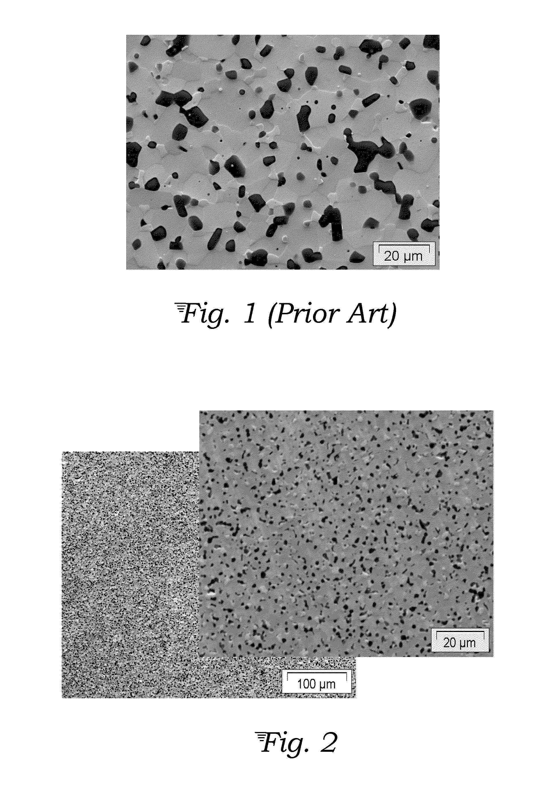
[0029]FIG. 1 shows a baseline hot pressed UHTC microstructure of HfB2: 20 vol % SiC formed from powdered HfB2 and SiC. It can be seen that this known UHTC system does not have high aspect ratio SiC reinforcements.

[0030]FIG. 2 shows a spark plasma sintered (SPS) UHTC microstructure of HfB2: 10 vol % SiC formed from a mixture of powdered HfB2 and a pre-ceramic polymer. The SPS process pulses electric current through a graphite die containing the ceramic mixture, thus generating heat internally at a very fast rate. It can be seen in FIG. 2 that this SPS processing results in a very refined microstructure, but no evidence of acicular reinforcing grains.

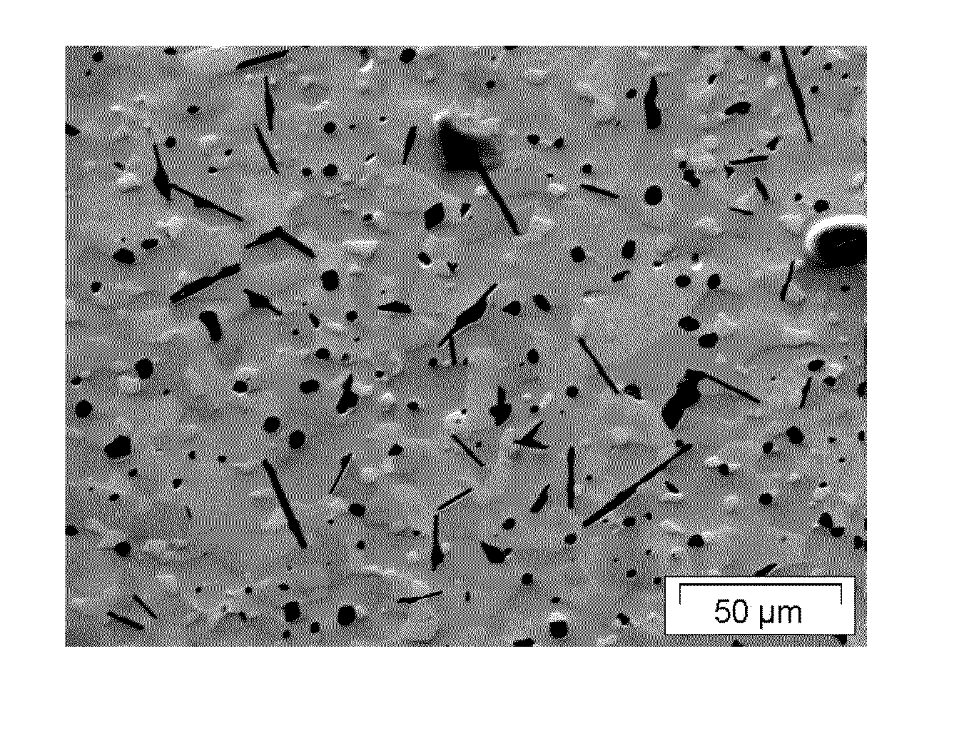
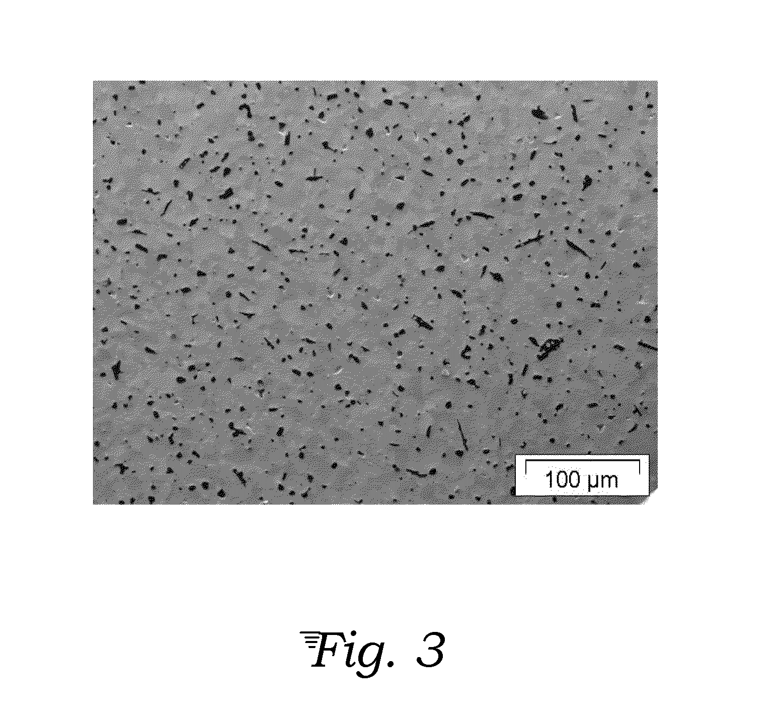
[0031]FIG. 3 shows hot pressed microstructure of HfB2: 10 vol % SiC formed from a mixture of powdered HfB2 and a pre-ceramic polymer, but at a dwell time of less than the minimum 30 minutes. It can be seen that short hot pressing times result in few acicular grains.

[0032]FIGS. 4-7 show hot pressed microstructures of HfB2: SiC formed from ...


PUM

PropertyMeasurementUnit
melting temperatureaaaaaaaaaa
pressureaaaaaaaaaa
temperatureaaaaaaaaaa

Abstract

A tough ultra-high temperature ceramic (UHTC) composite comprises grains of UHTC matrix material, such as HfB2, ZrB2 or other metal boride, carbide, nitride, etc., surrounded by a uniform distribution of acicular high aspect ratio reinforcement ceramic rods or whiskers, such as of SiC, is formed from uniformly mixing a powder of the UHTC material and a pre-ceramic polymer selected to form the desired reinforcement species, then thermally consolidating the mixture by hot pressing. The acicular reinforcement rods may make up from 5 to 30 vol % of the resulting microstructure.

Description

STATEMENT REGARDING FEDERALLY SPONSORED RESEARCH OR DEVELOPMENT[0001]The invention described herein was made in the performance of work under NASA contract nos. NNA 04BC25C and NNA 05CS57A and is subject to Public Law 96-517 (35 U.S.C. 200 et seq.). The contractor has not elected to retain title to the invention.TECHNICAL FIELD[0002]The invention generally relates to ceramic compositions and processes of obtaining a ceramic product, especially ultra-high temperature ceramics. The invention more particularly relates to consolidated ceramic composites comprising a microstructure of a ceramic matrix incorporating a reinforcing ceramic phase, with emphasis on processes of obtaining uniform distribution of the reinforcing phase and controlling the growth of these phases.BACKGROUND ART[0003]The potential of various materials for use on reusable space transport vehicles with sharp leading edges is being investigated. The sharp leading edges (e.g., at the nose and wing edges) of these vehic...

Claims


Application Information

Patent Timeline
Patent Type & Authority Patents(United States)
IPC IPC(8): B28B1/00B32B19/00B32B9/00C04B35/00C04B33/32B28B5/00B28B3/00
CPCC04B35/58078B28B3/025C04B35/62834C04B35/645C04B35/806C04B35/62655C04B2235/3813C04B2235/3826C04B2235/483C04B2235/486C04B2235/524C04B2235/5244C04B2235/5276C04B2235/6567C04B2235/666C04B35/80
Inventor STACKPOOLE, MARGARET MGASCH, MATTHEW JOLSON, MICHAEL WHAMBY, IAN W.JOHNSON, SYLVIA M
Owner NASA
Why Eureka
Try Eureka