
Method and system for wasteless processing and complete utilization of municipal and domestic wastes

a technology of municipal and domestic waste and wasteless processing, applied in the field of waste treatment, can solve the problems of unburned chemicals, unburned chemicals, and new chemicals, and achieve the effects of reducing the amount of was

Active Publication Date: 2013-04-16
GREENLIGHT ENERGY SOLUTIONS
View PDF19 Cites 26 Cited by
  • Summary
  • Abstract
  • Description
  • Claims
  • Application Information

AI Technical Summary

Benefits of technology

[0024]It is an object of the invention to provide a novel method and system for wasteless pyrolytic processing and complete utilization of municipal and domestic wastes. It is another object to provide the aforementioned system that allows a high degree of purification of gas and more efficient generation of energy in gas-turbine co-generators. It is a further object to provide the aforementioned method and system that separate CO2 from the syngas and utilize the separated CO2 as an additional commercial product along with decrease in concentration of harmful components in the gas exhausted to the atmosphere. Still another object is to provide the aforementioned system that does not require separate collection of wastes of different types. One more object is to provide the above system that does not leave by-products such as a coking residue. Still another object is to provide the aforementioned system that is capable of working in a self-contained mode and at the same time producing energy for external consumers.
[0027]Mechanisms of loading of the wastes into the pyrolysis reactor and of unloading of solid products of the reaction, such as coke, are similar to each other in that each of these mechanisms comprises an upper and lower slide valves or gates. Waste loading mechanism is installed on the front or proximal cover of the pyrolysis reactor, and the coke unloading mechanism is installed on the rear or distal cover of the pyrolysis reactor. The wastes fall from the waste accumulator onto the closed upper gate. Then the upper gate is opened, and the wastes fall onto the lower gate. After accumulation of a predetermined amount of the wastes, the upper gate is then closed, and the lower gate is opened allowing the wastes to fall onto the loading screw that moves the wastes to a spring-loaded gate. When the wastes are compacted to a degree that exceeds the holding threshold of the spring-loaded gate, the latter is shifted away under waste pressure and let the load to enter the space between the thread surfaces of the waste-feeding screws inside the interior of the retort. Such a two-gate spring-loaded gate prevents small particles of the wastes from *being carried away into the oxidizer without being pyrolyzed, decreases penetration of oxygen-containing atmospheric air into the retort. The waste-feeding screws have a variable pitch, which decreases in the direction of movement of the material. This allows for reducing the volume occupied by the wastes and thus to reduce the volume of air in the wastes. The air-displacement force is adjusted by the mass of a cover secured on an axle.

Problems solved by technology

The disposal of municipal, industrial, agricultural and other types of wastes is a problem that continues to grow with the increase of population and with growth of production, especially in the industrially developed countries.
However, along with elimination of the wastes, incinerators generate very toxic gases.
Moreover, incinerator ashes are contaminated with heavy metals, unburned chemicals, and new chemicals formed during the burning process.
Although the heat generated by the apparatus is reused in the waste-processing system, the apparatus does not generate thermal energy as its final product.
Another disadvantage is that gas produced in the process is discharged into the atmosphere without preliminary cleaning.
The system is provided with a dryer that uses solar energy, which significantly limits the areas where the system can be used.
Although the gas is cleaned in several steps, the system does not provide cleaning from CO2, and this does not allow increase of the calorie-content in the produced gaseous fuel.
However, the system is designed only for afterburning of the gas and does not teach the subsequent use of the gaseous product as a fuel for a power generator.
Although the waste feeder is made in the form of two parallel augers, the latter transport the wastes without effective mixing.
The wastes are moved without effective mixing.
However, the system is not provided with a material crusher and dryer.
The amount of municipal solid wastes normally collected by a municipality may be inadequate in volume to produce enough fuel gas with which to generate electricity sufficient to serve the entire community.
The patent does not teach utilization of the coke residue that remains after the process.
A disadvantage of plasma pyrolysis systems is that such systems require gasification of solid wastes which is associated with additional expenses.
Another problem is associated with the generation of hazardous gases such as dioxins and furanes which are formed after cooling of the plasma products to a temperature below 500° C., if the wastes were treated at temperature above 1200° C. for less than 2 sec.
Another disadvantage of plasma systems is that such systems work at temperature of 2500 C to 5000 C. Such temperatures deteriorate structural materials of the system and lead to frequent and expensive maintenance and repairs.
However, in some cases the syngas is used as a component for a mixture with biogas without pre-cleaning, and in other cases the syngas is not separated from CO2 and therefore has low energy-generation efficiency.
Another disadvantage of the known waste-processing systems is a lack of an efficient mechanism for feeding and mixing materials in pyrolysis chambers, a relatively high metal-to-power ratio in the structure of the pyrolysis chamber and, hence, high manufacturing cost, and incomplete cleaning of the gases, which are exhausted through the upper channel of the chamber together with the syngas, from fine waste particles.

Method used


Image

  • Method and system for wasteless processing and complete utilization of municipal and domestic wastes
  • Method and system for wasteless processing and complete utilization of municipal and domestic wastes
  • Method and system for wasteless processing and complete utilization of municipal and domestic wastes

Examples


Embodiment Construction

[0054]As has been mentioned above, the invention relates to a method and system for processing and utilizing solid municipal and domestic wastes by pyrolytic treatment.

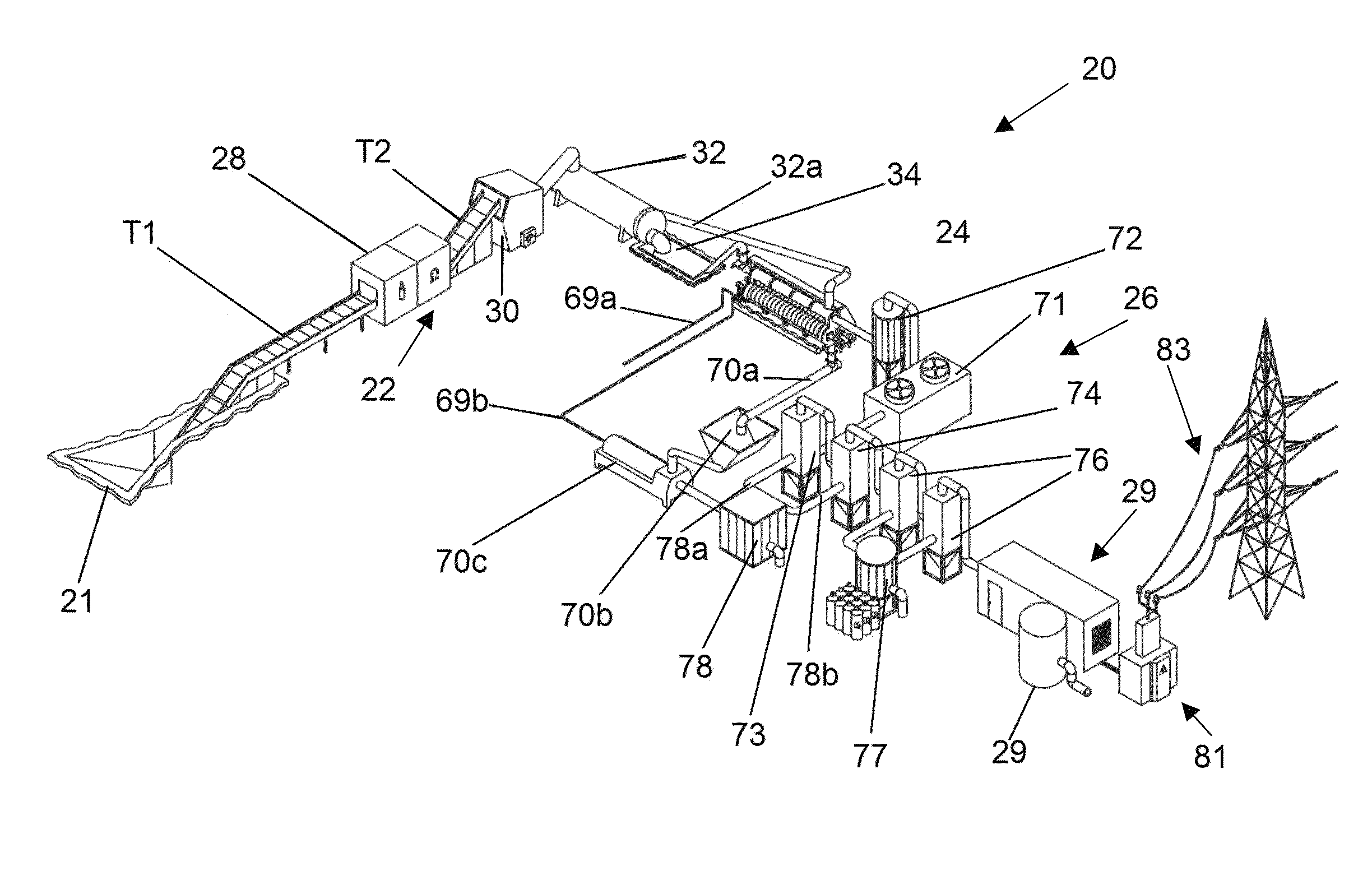
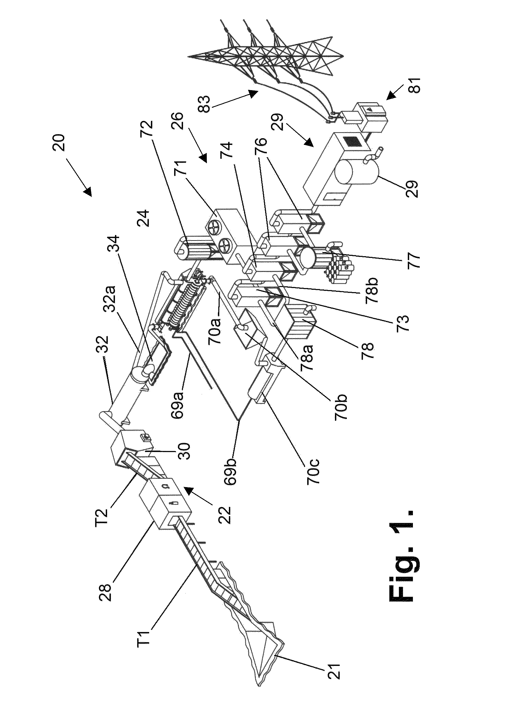
[0055]A block-diagram of the system of the invention for processing and utilizing solid municipal and domestic wastes by pyrolytic treatment is shown in FIG. 1.

[0056]The system, which as a whole is designated by reference numeral 20, comprises the following main modules connected in series: a waste pre-treatment and feed module 22, a pyrolysis reactor 24, a syngas cleaning module 26, and an energy generation unit 29.

[0057]The waste pre-treatment and feed module 22, in turn, consists of a waste reception site 21, a linear conveyor T1, a waste-sorting unit or a sorter 28 that received the untreated wastes from the linear conveyor T1 and is capable of sorting untreated wastes and simultaneously removing those waste components that have low energy potential and do not contain hydrocarbons. In this unit, the sorted wastes ...


PUM

PropertyMeasurementUnit
temperatureaaaaaaaaaa

Abstract

Proposed are a system and method for wasteless pyrolytic processing and complete utilization of municipal and domestic wastes. The wastes are sequentially passed through units of sorting, grinding, drying, accumulating, and sending to a pyrolysis reactor for pyrolytic treatment. The syngas produced in the pyrolysis is passed through dry cleaning, dust catching, a first wet cleaning with water, a second wet cleaning with alkali, and a floatation unit for separation of water which is purified to an extent sufficient for technical use. The purified syngas is also passed through an absorber and is then used as a working medium for a power generation unit such as a gas turbine co-generator that generates electricity. Solid products of the pyrolysis reaction, such as coke, are returned to the reactor for afterburning, and the heat of the reaction can be utilized in a dryer, or the like.

Description

FIELD OF THE INVENTION[0001]The present invention relates to treatment of wastes, and more particularly, to a method and system for wasteless processing and complete utilization of solid municipal and domestic wastes by pyrolytic treatment.BACKGROUND OF THE INVENTION[0002]The disposal of municipal, industrial, agricultural and other types of wastes is a problem that continues to grow with the increase of population and with growth of production, especially in the industrially developed countries.[0003]The USA generates 11 billion tons (10 billion metric tons) of solid wastes each year. Solid wastes are waste materials that contain less than 70% water. This class includes such materials as household garbage, some industrial wastes, some mining wastes, and oilfield wastes such as drill cuttings. Liquid wastes are usually wastewaters that contain less than 1% solids. Such wastes may contain high concentrations of dissolved salts and metals. Sludge is a class of wastes between liquid an...

Claims


Application Information

Patent Timeline
Patent Type & Authority Patents(United States)
IPC IPC(8): C10B1/00C10B7/10C10J1/207
CPCC10K1/101C10K1/103C10K1/12C10B47/44C10B53/00F02C3/28F23G5/006F23G5/02F05D2220/75Y02E20/12Y02E50/12F23G2201/10F23G2201/301F23G2201/303F23G2201/304F23G2201/40F23G2201/602F23G2201/603F23G2201/80F23G2205/121F23G2206/202F23G2206/203Y02E50/10
Inventor FEERER, ARKADYKULAKOV, MARAT HASBULATOVICHZAGORSKY, DENIS
Owner GREENLIGHT ENERGY SOLUTIONS
Learn More