
Manufacturing method of SOI substrate

a manufacturing method and substrate technology, applied in the direction of semiconductor devices, electrical equipment, transistors, etc., can solve the problems of non-uniform heat distribution in the base substrate, difficult to achieve the size increase of conventional soi substrates, and the inability to allow the single crystal semiconductor layer to be uniform in quality, so as to achieve the effect of improving the productivity of a semiconductor device such as a semiconductor integrated circui

Inactive Publication Date: 2013-04-30
SEMICON ENERGY LAB CO LTD
View PDF26 Cites 15 Cited by
  • Summary
  • Abstract
  • Description
  • Claims
  • Application Information

AI Technical Summary

Benefits of technology

The present invention is a manufacturing method for a substrate that has a plurality of single crystal semiconductor layers. The method ensures uniform quality of the layers over a larger area than a single crystal silicon substrate. This substrate can be used to improve productivity in the production of semiconductor devices, such as semiconductor integrated circuits. The method achieves this by using a tray with a depression portion for the base substrate that supports the semiconductor layers, which ensures uniform heat distribution during the heat treatment process. The tray also has a supporting portion between the depression portions to reduce the contact area with the base substrate. By using this method, a larger number of high-quality semiconductor layers can be formed over a larger substrate, which improves productivity in semiconductor device production.

Problems solved by technology

However, the size of a conventional SOI substrate depends on the size of a single crystal silicon wafer and it is difficult to achieve size increase for conventional SOI substrates.
The area of an SOI substrate can be increased by bonding a plurality of single crystal silicon wafers to a large-area base substrate with the use of a holding tray and performing separation using a hydrogen ion implantation separation method; however, even in that case, there is a problem in that a difference arises between the single crystal silicon wafers in the separation of single crystal semiconductor layers, which does not allow the single crystal semiconductor layers to be uniform in quality.
It is considered that this is mainly because the heat distribution in the base substrate and the single crystal silicon wafers becomes non-uniform when a heat treatment is performed to separate the single crystal semiconductor layers from the single crystal silicon wafers which are bonded to the base substrate.

Method used


Image

  • Manufacturing method of SOI substrate
  • Manufacturing method of SOI substrate
  • Manufacturing method of SOI substrate

Examples


embodiment 1

[0042]In this embodiment, an SOI substrate in which a plurality of single crystal semiconductor layers is provided over a substrate and a manufacturing method thereof are described.

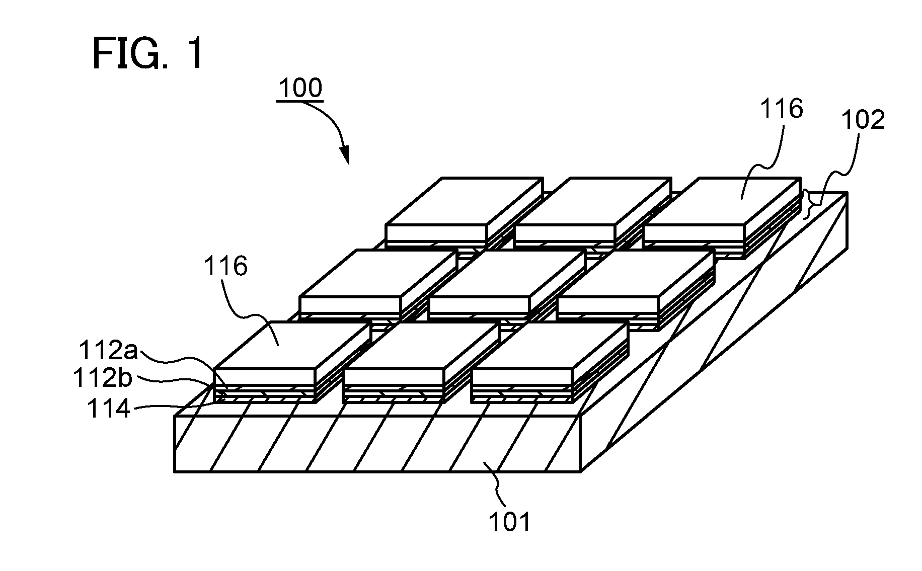
[0043]FIG. 1 is a perspective view illustrating a structural example of an SOI substrate 100. In the SOI substrate 100, a plurality of single crystal semiconductor layers 116 is bonded to a base substrate 101. Each of the single crystal semiconductor layers 116 is provided over the base substrate 101 with an insulating layer 102 interposed therebetween, and the SOI substrate 100 is a so-called semiconductor substrate with an SOI structure.

[0044]The insulating layer 102 may have a single-layer structure or a stacked-layer structure. In this embodiment, the insulating layer 102 has a three-layer structure in which a bonding layer 114, an insulating film 112b, and an insulating film 112a are stacked in this order from the base substrate 101 side.

[0045]The single crystal semiconductor layer 116 is formed by t...

embodiment 2

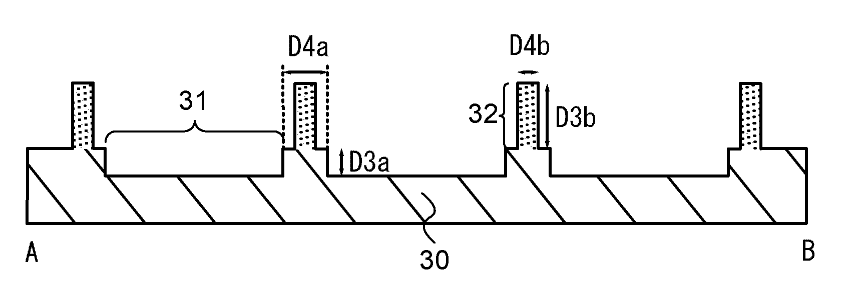
[0163]In this embodiment, a manufacturing method of an SOI substrate in which a plurality of single crystal semiconductor layers are provided over a substrate is described in the case where a tray different from that in Embodiment 1 is used at the time of a heat treatment for separating single crystal semiconductor substrates.

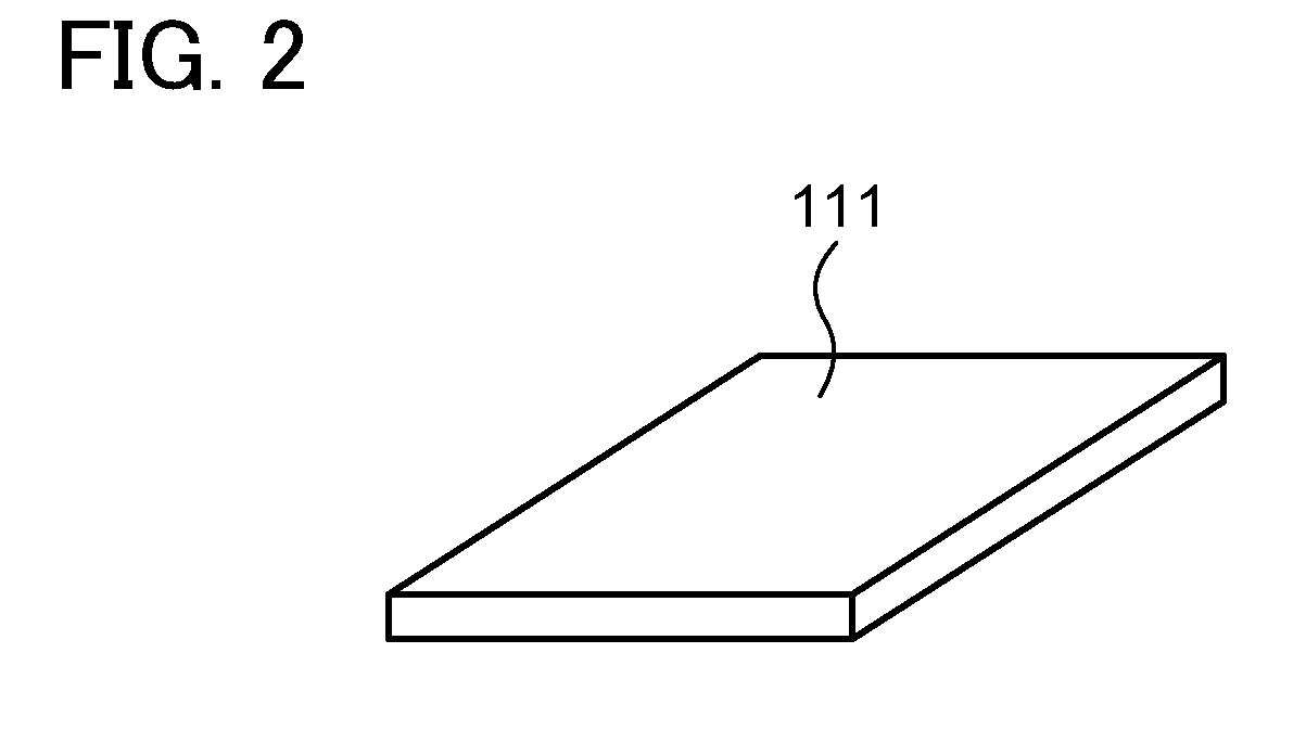
[0164]First, in a manner similar to that in Embodiment 1, the single crystal semiconductor substrates 111 are bonded to the base substrate 101 as illustrated in FIG. 8A.

[0165]Then, as illustrated in FIG. 12A, the first tray 10, which is used in bonding the single crystal semiconductor substrates 111, is detached from the single crystal semiconductor substrates 111 and the base substrate 101 and a third tray 30 is disposed. Note that in this embodiment, the tray which is used after the first tray is called the third tray 30 so as to be distinguished from the second tray 20 which is used in Embodiment 1.

[0166]FIGS. 13A and 13B are an external view and a cross-sec...

embodiment 3

[0185]In Embodiment 3, a regenerating treatment of a single crystal semiconductor substrate will be described. Here, the single crystal semiconductor substrate 117 illustrated in FIG. 8C and FIG. 12B, from which the single crystal semiconductor layer 115 is separated, is regenerated. The regenerating treatment for the single crystal semiconductor substrate will be described with reference to FIGS. 14A to 14D.

[0186]After the steps of FIG. 8C and FIG. 12B, as illustrated in FIG. 14A, the projection portion 130 is formed at the peripheral portion of the single crystal semiconductor substrate 117. The projection portion 130 includes the remaining embrittlement layer 133, the remaining single crystal semiconductor layer 135, the remaining insulating layer 132 (the remaining insulating film 132b and the remaining insulating film 132a) and the remaining bonding layer 134, which are not bonded to the base substrate 101.

[0187]First, an etching treatment is performed to remove the remaining i...


PUM

PropertyMeasurementUnit
sizesaaaaaaaaaa
sizesaaaaaaaaaa
sizesaaaaaaaaaa

Abstract

An object is to provide a manufacturing method of an SOI substrate in which a plurality of single crystal semiconductor layers uniform in quality is bonded to a substrate having a larger area than a single crystal silicon substrate. At the time of a heat treatment, uniform heat distribution in single crystal semiconductor substrates is realized by using a tray which has depression portions each with a large depth and is not in contact with the single crystal semiconductor substrate bonded to a base substrate as a tray for supporting the base substrate and holding the single crystal semiconductor substrates. Further, by providing a supporting portion for the base substrate between the depression portions of the tray, a contact area between the tray and the base substrate is reduced.

Description

BACKGROUND OF THE INVENTION[0001]1. Field of the Invention[0002]The present invention relates to a manufacturing method of a substrate provided with a semiconductor layer with an insulating film interposed therebetween, particularly, a silicon-on-insulator (SOI) substrate.[0003]2. Description of the Related Art[0004]In recent years, integrated circuits that use a silicon on insulator (SOI) substrate in which a thin single crystal semiconductor layer is provided on an insulating surface, instead of a bulk silicon wafer, have been developed. By utilizing characteristics of a thin single crystal silicon film formed over an insulating film, transistors formed in the integrated circuit can be separated from each other completely. Further, since fully-depleted transistors can be formed, a semiconductor integrated circuit with high added value such as high integration, high speed driving, and low power consumption can be realized.[0005]As one of the manufacturing methods of SOI substrates,...

Claims


Application Information

Patent Timeline
Patent Type & Authority Patents(United States)
IPC IPC(8): H01L21/22
CPCH01L21/76254H01L27/1266H01L27/1214H01L27/1203
Inventor MORIWAKA, TOMOAKI
Owner SEMICON ENERGY LAB CO LTD
Learn More