
Jammer detection based adaptive PLL bandwidth adjustment in FM receiver

a technology of adaptive pll bandwidth and fm receiver, which is applied in the direction of substation equipment, electrical equipment, pulse automatic control, etc., can solve the problems of limited audio output quality of fm receiver, inability to adjust the bandwidth of fm receiver, and inability to detect jamming, so as to reduce in-band residual fm, high loop bandwidth, and high pll loop bandwidth

Active Publication Date: 2013-05-07
QUALCOMM INC
View PDF15 Cites 5 Cited by
  • Summary
  • Abstract
  • Description
  • Claims
  • Application Information

AI Technical Summary

Benefits of technology

The patent describes a method for improving the performance of a RF receiver by automatically adjusting the bandwidth of the PLL (phase locked loop) based on the detection of a jammer or a specific signal in the out-of-band SSB (semi-symmetrical single sideband) phase noise. This allows for optimal performance in both in-band residual FM and out-of-band SSB phase noise without compromising the performance of other sub-circuits. Additionally, by reducing the power consumption and size of the VCO (voltage controlled oscillator) and improving its phase noise performance, the overall size and power consumption of the FM receiver is reduced.

Problems solved by technology

The quality of audio output by an FM receiver is generally limited by the in-band residual FM.
When a jammer is present, however, then the quality of the audio output by the FM receiver is generally limited by out-of-band SSB phase noise.
The jammer and the wanted signal being received are FM demodulated, giving rise to audio distortion due to reciprocal mixing.
This audio distortion dominates the deleterious effect of the in-band residual FM phase noise.
In one example, a jammer is a signal that is of such a frequency and power that it reciprocally mixes with phase noise of the LO signal in the receiver in such a way that substantial in-band signal-to-noise degradation results.
For example, achieving low Voltage Controlled Oscillator (VCO) phase noise often requires that the VCO sub-circuit within the PLL consume a relatively large amount of power or that a large layout area high quality factor spiral inductor be used in the LC tank of the VCO.

Method used


Image

  • Jammer detection based adaptive PLL bandwidth adjustment in FM receiver
  • Jammer detection based adaptive PLL bandwidth adjustment in FM receiver
  • Jammer detection based adaptive PLL bandwidth adjustment in FM receiver

Examples


Embodiment Construction

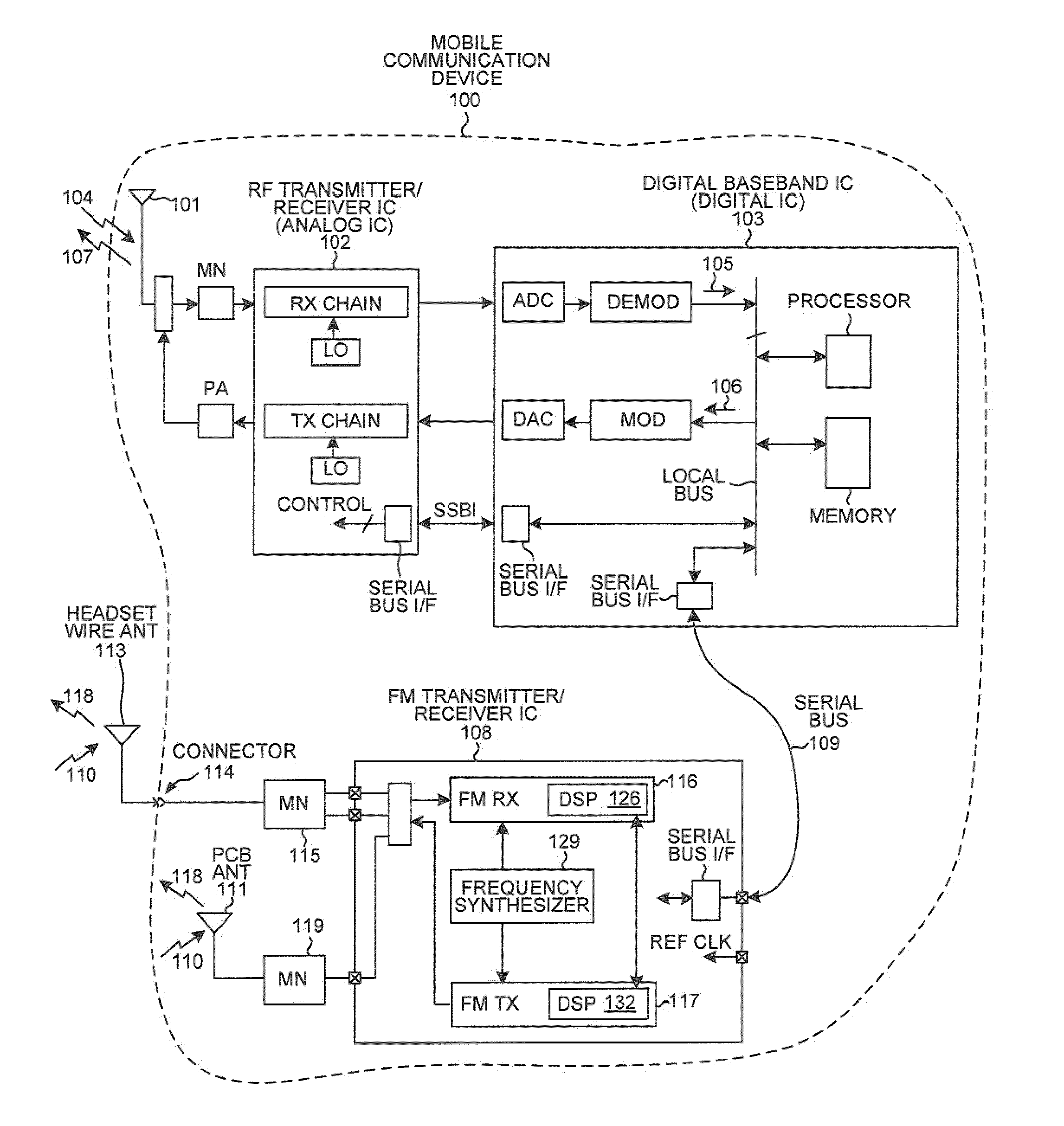
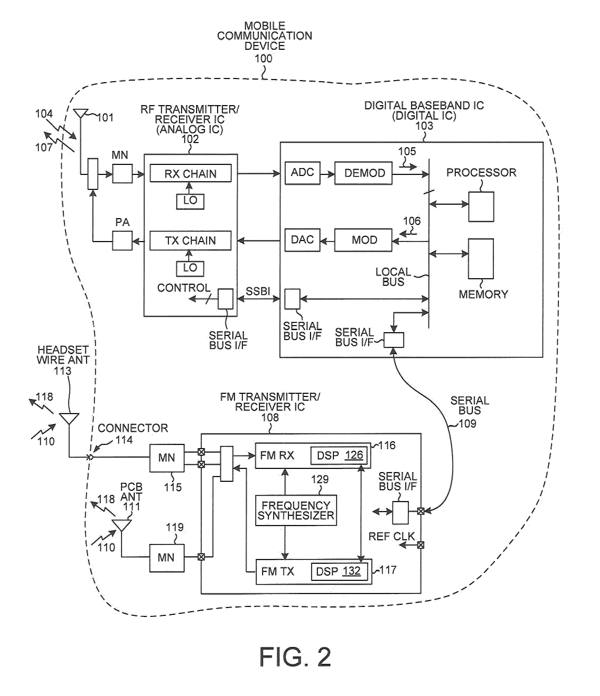
[0031]FIG. 2 is a very simplified high level block diagram of one particular type of mobile communication device 100 that carries out a Phase-Locked Loop (PLL) bandwidth adjustment method in accordance with one aspect. In the present example, mobile communication device 100 is a battery-powered handheld device such as a cellular telephone. Cellular telephone 100 includes (among other parts not illustrated) an antenna 101 usable for receiving and transmitting cellular telephone communications, an RF transceiver integrated circuit 102, and a digital baseband integrated circuit 103. In one very simplified explanation of the operation of the cellular telephone, if the cellular telephone is being used to receive audio information as part of a cellular telephone conversation, then an incoming transmission 104 is received on antenna 101. The signal is amplified and downconverted and filtered in RF transceiver integrated circuit 102. After being digitized, demodulated and decoded in digital...


PUM


Abstract

A frequency synthesizer within an FM receiver employs a Phase-Locked Loop (PLL) to generate a Local Oscillator (LO) signal. The LO signal is supplied to a mixer. The FM receiver also includes jammer detection functionality. If no jammer is detected, then the loop bandwidth of the PLL is set to have a relatively high value, thereby favoring suppression of in-band residual FM. If a jammer is detected, then the loop bandwidth of the PLL is set to have a relatively low value, thereby favoring suppression of out-of-band SSB phase noise. By adaptively changing loop bandwidth depending on whether a jammer is detected, performance requirements on sub-circuits within the PLL can be relaxed while still satisfying in-band residual FM and out-of-band SSB phase noise requirements. By allowing the VCO of the PLL to generate more phase noise due to the adaptive changing of loop bandwidth, VCO power consumption can be reduced.

Description

BACKGROUND INFORMATION[0001]1. Technical Field[0002]The present disclosure relates to Phase-Locked Loop (PLL) based frequency synthesizers within Frequency Modulation (FM) receivers.[0003]2. Background Information[0004]A miniaturized and integrated FM (Frequency Modulation) radio transceiver generally involves the use of a frequency synthesizer. The frequency synthesizer typically includes a Phase-Locked Loop (PLL) and therefore may be referred to as a PLL-based frequency synthesizer. If, for example, an integrated FM radio transceiver is receiving a radio transmission, then the PLL-based frequency synthesizer within the transceiver generates a Local Oscillator (LO) signal. The LO signal is supplied to a mixer that is part of a demodulator of an FM receiver portion of the transceiver. If, on the other hand, the FM radio transceiver is transmitting a radio transmission, then the same PLL-based frequency synthesizer is used to output an FM modulated signal. The FM modulated signal is ...

Claims


Application Information

Patent Timeline
Patent Type & Authority Patents(United States)
IPC IPC(8): H04B1/06H04B7/00
CPCH04B1/1027H03L7/107H04B1/10
Inventor ZENG, YIPAN, TZU-WANGLIN, I-HSIANGDUNWORTH, JEREMYTRIKHA, PUSHPAPTE, RAHUL
Owner QUALCOMM INC
Learn More