Power supply controller

a power supply controller and controller technology, applied in the direction of electric vehicles, process and machine control, emergency protective circuit arrangements, etc., can solve the problems of large-scale charging circuits, complicated driver circuits, low cost, and light weight, and achieve easy modularization, easy provision, and reduced size and weight

Inactive Publication Date: 2013-06-04
JAPAN AEROSPACE EXPLORATION AGENCY +1
View PDF17 Cites 0 Cited by
  • Summary
  • Abstract
  • Description
  • Claims
  • Application Information

AI Technical Summary

Benefits of technology

[0014]In recent years, a power supply controller for artificial satellite has been required to have a small size, light weight, high reliability, and low cost. However, in the power supply controller illustrated in FIG. 5, the shunt circuits and the charging circuit are intensively controlled by the driver circuit having the redundant structure to avoid a total loss due to the failure of a single part, and hence there is a problem that the driver circuit is complicated and thus it is difficult to realize a small size, light weight, and low cost. In a case where short-term rapid charging is necessary, such as a case of the low-earth orbit satellite, there is also a problem that a large-scale charging circuit is required so as to fully charge the battery without stress.
[0018]Therefore, it is an object of this invention to provide a power supply controller which realizes at least one of (1) a point that a shunt circuit and a charging circuit are reduced in size and weight, (2) a point that the shunt circuit and the charging circuit are modularized and improved in reliability, (3) a point that full charge may be achieved by large-current rapid charging without stress to a battery, (4) a point that generated powers of solar cells are not reduced even during charging of the battery, and (5) charging power may be supplied to a load after the completion of the charging.
[0020]According to one aspect of this invention, the shunt circuits and the charging circuit are separately and independently operated based on the preset threshold values. Therefore, (1) a driver circuit (redundant structure) for the shunt circuits and the charging circuit may be omitted and reduced in size and weight. In addition, (2) the shunt circuits and the charging circuit are electrically separated from one another and thus are not affected by failure, and are easily modularized and thus easily provided corresponding to an increase and reduction in treatment power. Further, (3) a charging current may be reduced stepwise with an increase in battery voltage, and hence the full charge may be achieved by the large-current rapid charging without stress to the battery. Further, (4) the charging circuit may be on-off controlled to stabilize a bus voltage, and hence the generated powers of the solar cells are not reduced even during the charging of the battery (SHNT mode and BCC mode). Further, (5) after the completion of the charging, the charging circuit may be stopped to supply the charging power to the load.

Problems solved by technology

However, in the power supply controller illustrated in FIG. 5, the shunt circuits and the charging circuit are intensively controlled by the driver circuit having the redundant structure to avoid a total loss due to the failure of a single part, and hence there is a problem that the driver circuit is complicated and thus it is difficult to realize a small size, light weight, and low cost.
In a case where short-term rapid charging is necessary, such as a case of the low-earth orbit satellite, there is also a problem that a large-scale charging circuit is required so as to fully charge the battery without stress.
The power supply controller illustrated in FIG. 6 has a problem that it is difficult to perform large-current rapid charging without stress to the battery because the charging circuit is simple but cannot perform constant voltage charging.
In addition, the power supply controller has a problem that the output power of the solar cell reduces because a charge array voltage during charging lowers to substantially a battery voltage.
The power supply controller described in Patent Document 2 does not include the battery, and hence the problems on charging as described above may not be solved.
In the power supply controller described in Patent Document 3, the shunted outputs of the solar cell array are supplied to the battery, and hence there is a problem that a charging current changes depending on a state of the load and thus stable charging may not be performed.

Method used


Image

  • Power supply controller
  • Power supply controller
  • Power supply controller

Examples


first embodiment

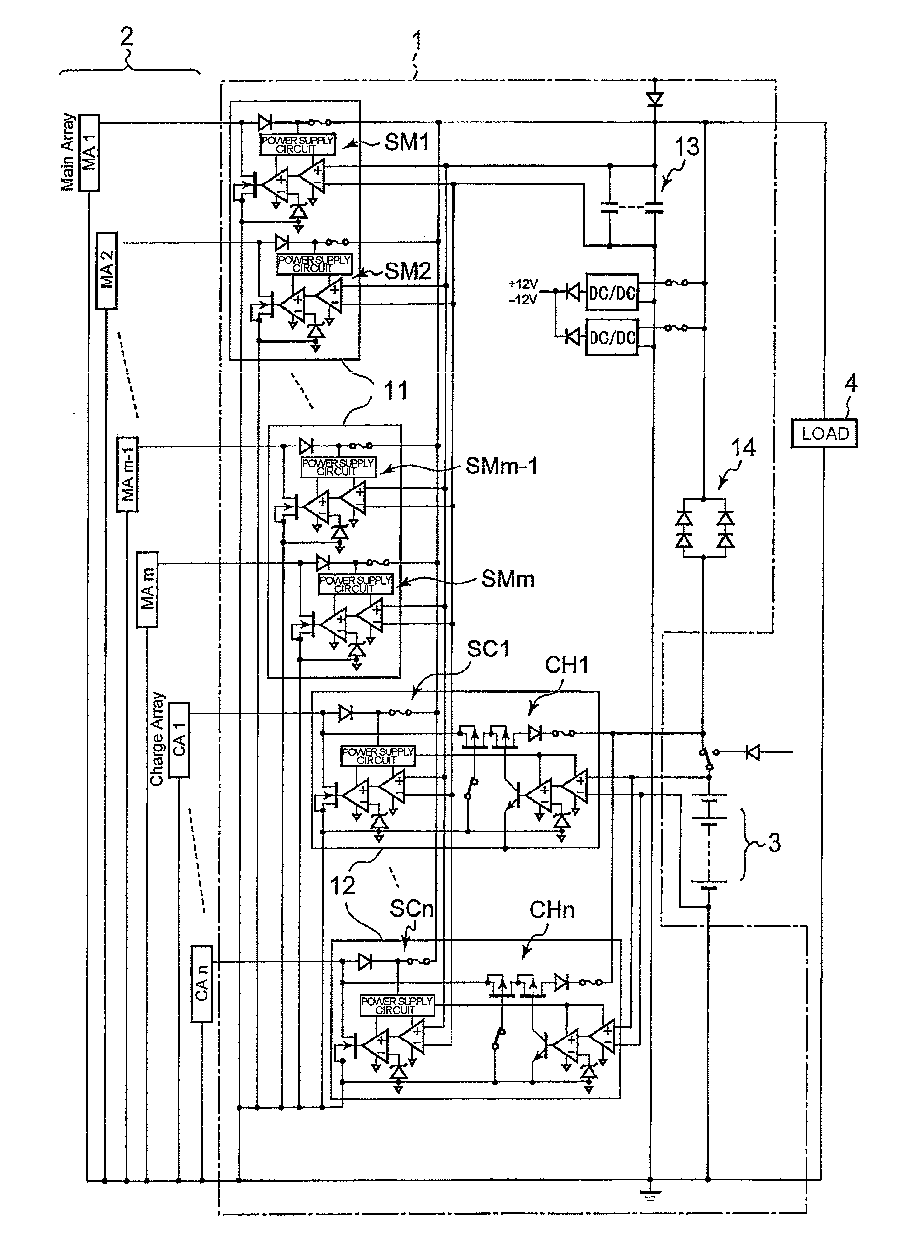
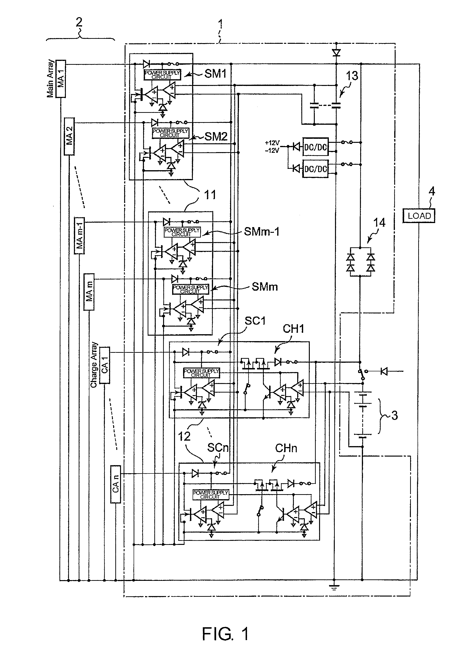
[0028]FIG. 1 illustrates a circuit structure of a (distributed control type) power supply controller 1 according to this invention. The power supply controller 1 is used for a power supply system and device using a solar cell and a battery as power sources, particularly, for a power supply system of a space craft such as an artificial satellite.

[0029]The power supply controller 1 is connected to a plurality of solar cells 2, a battery 3, and a load 4 and includes a plurality of MA modules 11, a plurality of CA modules 12, a capacitor bank 13, and a discharge diode 14.

[0030]The MA modules 11 each include two shunt circuits which are modularized. Shunt circuits SM1 to SMm (m is natural number) are separately connected to corresponding main arrays MA1 to MAm of the plurality of solar cells 2, which are used for only power supply to the load 4. Each of the shunt circuits includes a diode, a fuse, a power supply circuit, an operational amplifier, a comparator, a transistor switch, and a ...

second embodiment

[0063]Next, a power supply controller according to this invention is described with reference to FIG. 4.

[0064]The power supply controller illustrated in FIG. 4 is a power supply controller in which the discharge diode 14 illustrated in FIG. 1 is replaced by a battery discharge regulator (BDR) unit 41. Even in the shade case (BAT mode), the stabilization may be achieved so as to obtain substantially almost the same bus voltage as in the sunshine case by the action of the BDR unit 41.


PUM

PropertyMeasurementUnit
thresholdaaaaaaaaaa
voltageaaaaaaaaaa
output voltageaaaaaaaaaa

Abstract

Main arrays (MA1-MAm) of solar cells (2) are provided so as to correspond to shunt circuits (SM1-SMm), respectively. Charge arrays (CA1-CAn) are provided so as to correspond to shunt circuits (SC1-SCn) and charging circuits (CH1-CHn), respectively. Each shut circuit operates independently from other shunt circuits, and each charging circuit operates independently from other charging circuits.

Description

TECHNICAL FIELD[0001]This invention relates to a power supply controller, and more particularly, to a power supply controller for controlling power supply from a plurality of solar cell arrays and a battery to a load.BACKGROUND ART[0002]As illustrated in FIG. 5, an associated power supply controller is connected to a solar cell 51, a battery 52, and a load 53, and includes (a plurality of) shunt circuits 54, a driver circuit 55, a charging circuit 56, and a discharging circuit 57.[0003]In the power supply controller, an output voltage (bus voltage) of the solar cell 51 is stabilized by the shunt circuit 54 to be supplied to the load 53, and supplied to the charging circuit 56 to charge the battery 52. In order to realize constant current and constant voltage control, the charging circuit 56 includes a switching regulator (battery charge regulator (BCR)).[0004]The operation of the shunt circuit 54 and the charging circuit 56 is controlled by the driver circuit 55 having a redundant c...

Claims


Application Information

Patent Timeline
Patent Type & Authority Patents(United States)
IPC IPC(8): H02J7/34H01M10/44
CPCB64G1/428B64G1/443H02J7/35H01M10/441H01M10/44Y02E60/10
Inventor YOSHIDA, TEIJIGONDAI, TOMOTAKEKIBE, KOICHIKUSAWAKE, HIROAKINAITO, HITOSHISEGAMI, GO
Owner JAPAN AEROSPACE EXPLORATION AGENCY
Why Eureka
Try Eureka