Methods of making lithium ion battery separators

a lithium ion battery and separator technology, applied in the direction of electrical equipment, cell components, cell components, etc., can solve the problems of short circuit, low ion conductance, and inability to provide these types of polymers with a sufficient porosity across their thicknesses, so as to improve ionic conductance and improve thermal stability

Active Publication Date: 2013-06-25
GM GLOBAL TECH OPERATIONS LLC
View PDF5 Cites 37 Cited by
  • Summary
  • Abstract
  • Description
  • Claims
  • Application Information

AI Technical Summary

Benefits of technology

[0011]The hydrophobic-treated ceramic particles dispersed throughout the polymer slurry preferably have particle diameters of about 0.005 μm to about 15 μm and, most preferably, from about 0.05 μm to about 3 The hydrophobic treatment imposed on the ceramic particles is any process that renders their surfaces more hydrophobic relative to their natural prepared state. The hydrophobic treatment imparted to the ceramic particles provides them with a weak, non-wetting surface interface that promotes pore and gap formation in their immediate vicinity during precipitation of the polymer material. These weak surface interactions between the hydrophobic-treated ceramic particles and the precipitating polymer material help propagate the tortuous and interconnected network of pores that is coextensively defined throughout and across the polymer material matrix of the prepared separator. A specific and most preferred hydrophobic-treated ceramic particle is fumed (pyrogenic) silica that has been surface modified with organosilicon compounds by way of a silanol condensation reaction.
[0016]The prepared thin-film polymer separator includes opposed major face surfaces that define a separator thickness ranging from about 20 μm to about 50 μm. The types of engineering polymer materials used to fabricate the polymer material matrix (i.e., PEI, PVdF, etc.) offer better thermal stability at temperatures of 130° C. and above and improved ionic conductance in comparison to polyolefins such as polypropylene and polyethylene. The ability of the porous thin-film separator to accommodate a liquid electrolyte solution and, therefore, communicate lithium ions from one side to the other, is supported by the tortuous and interconnected network of pores that coextensively traverses the polymer material matrix and fluidly connects the opposed major face surfaces. The network of interconnected pores provides the polymer material matrix with a void volume that ranges from about 20% to about 80%.

Problems solved by technology

But lifetime and performance declines are a concern for an electrochemical battery cell that includes a polyolefin separator.
The temperature-initiated physical distortion of the polyolefin separator may ultimately permit direct electrical contact between the negative and positive electrodes and cause the electrochemical cell to short-circuit.
But the separator fabrication methods often used for polyolefin separators generally cannot provide these types of polymers with a sufficient porosity across their thickness.
The porosity of the separator is not a physical property to be taken lightly as it impacts the performance and longevity of the electrochemical battery cell.
A separator with insufficient porosity impedes lithium ion migration between the electrodes while a separator with too much porosity is susceptible lithium dendrite crossover from the negative electrode.

Method used


Image

  • Methods of making lithium ion battery separators
  • Methods of making lithium ion battery separators

Examples


example

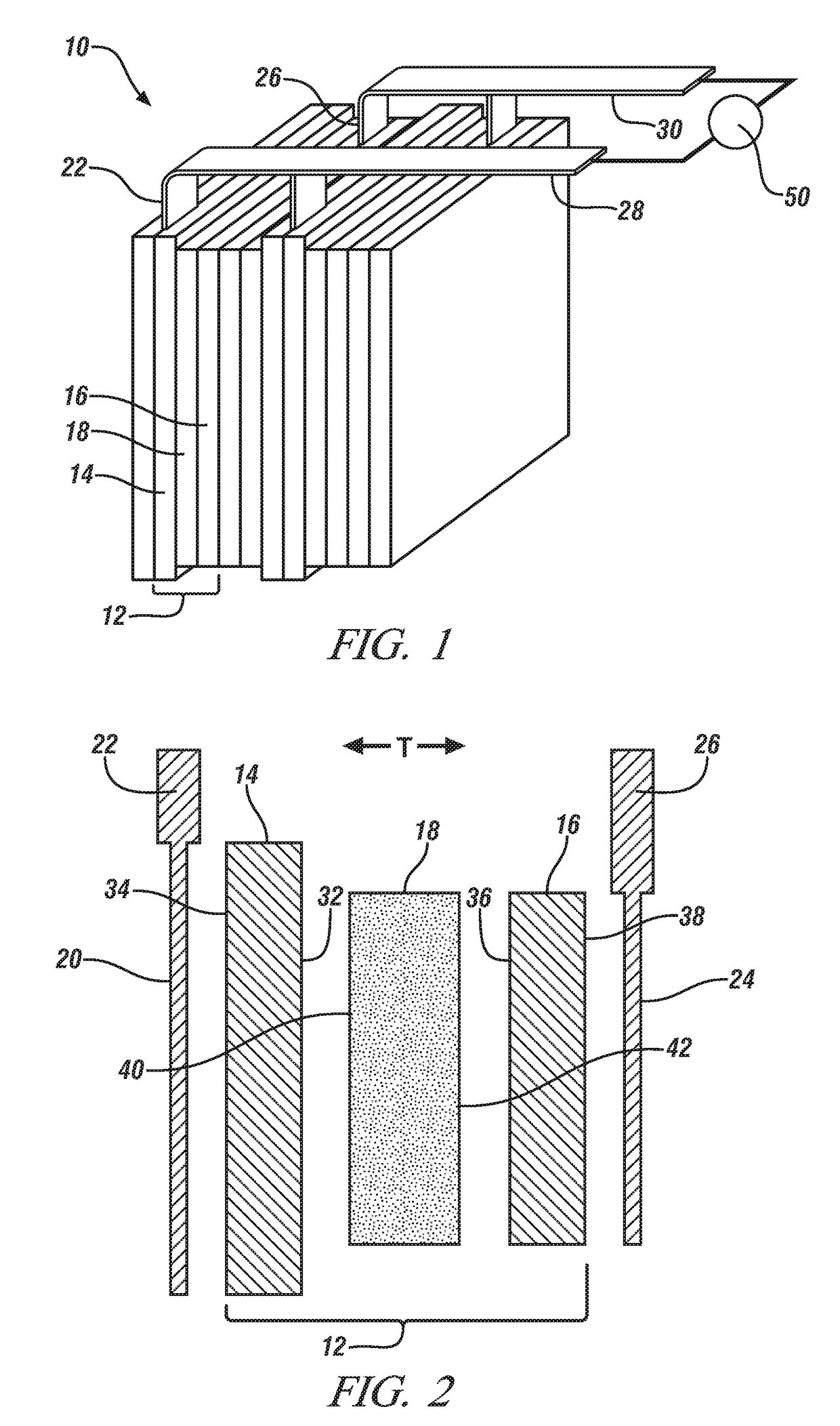
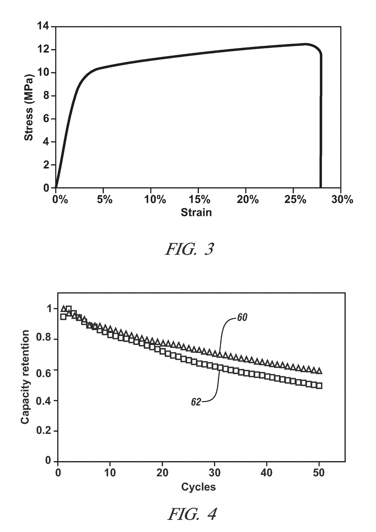
[0051]This Example demonstrates the tensile strength, ionic conductivity, and electrochemical cell cycle performance of a porous thin-film polymer separator, as described above, in comparison to a conventional monolayer polypropylene lithium ion battery separator obtained from Celgard, LLC (Charlotte, N.C.). The porous thin-film separator comprises a PEI polymer material matrix and a uniform internal dispersion of hydrophobic-treated fumed silica particles obtained from Cabot Corporation under the designation Cab-O-Sil®720. This particular separator is referred to in the remainder of this Example as the “inventive separator” for brevity.

[0052]The inventive separator was formed by a phase separation process in which a latent polymer solvent was used to make the polymer slurry. To begin, PEI was dissolved in dimethylformamide (DMF) at 90° C. followed by dispersion of the Cab-O-Sil®720 fumed silica particles. The resultant polymer slurry contained about 15 wt. % of the PEI and about 25...


PUM

PropertyMeasurementUnit
diametersaaaaaaaaaa
particle diametersaaaaaaaaaa
thicknessaaaaaaaaaa

Abstract

A porous thin-film polymer separator for use in a lithium ion battery may be formed by a phase separation method in which hydrophobic-treated ceramic particles are used to help induce the formation of a tortuous, interconnected network of pores coextensively across the thickness of the separator. As part of the phase separation method, a wet thin-film layer is formed from a polymer slurry that comprises a polymer solvent in which a polymer material is dissolved and the hydrophobic-treated ceramic particles are dispersed. The wet thin-film layer is subsequently exposed to a polymer non-solvent to form a solvent-exchanged thin-film precipitated polymer layer which is then heated to produce the separator.

Description

TECHNICAL FIELD[0001]The technical field of this disclosure relates generally to separators for a secondary lithium ion battery and, more specifically, to separators formed by a phase separation method. The use of small, hydrophobic-treated ceramic particles during the phase separation method helps form a tortuous, interconnected network of pores across the thickness of the resultant separator. In an electrochemical battery cell of a lithium ion battery, the separator is situated between confronting inner face surfaces of a positive electrode and a negative electrode and is soaked with a liquid electrolyte solution that can communicate lithium ions.BACKGROUND[0002]Secondary (i.e., rechargeable) lithium ion batteries have been implemented as a power source into a wide variety of stationary and portable applications. Their structure and electrochemical reaction mechanism provide them with several desirable characteristics including a relatively high energy density, a relatively low in...

Claims


Application Information

Patent Timeline
Patent Type & Authority Patents(United States)
IPC IPC(8): C08J9/00H01M2/16H01M50/406
CPCH01M2/166H01M2/145Y02E60/10H01M50/446H01M50/406
Inventor HUANG, XIAOSONG
Owner GM GLOBAL TECH OPERATIONS LLC
Why Eureka
Try Eureka