System and method for reduction of optical noise

a technology of optical noise reduction and optical sensing, applied in the field of optical sensing systems and methods, can solve the problems of generating false detection within the sensor, affecting the accuracy of target sensing, so as to improve the sensor performance

Active Publication Date: 2013-07-09
ROCKWELL AUTOMATION TECH
View PDF13 Cites 12 Cited by
  • Summary
  • Abstract
  • Description
  • Claims
  • Application Information

AI Technical Summary

Benefits of technology

[0008]The present inventor has recognized the aforementioned disadvantages associated with conventional optical or photoelectric sensors and related sensing processes, and has further recognized that the implementation of a phosphor-based layer in relation to an optical / photoelectric sensor (for example, within a transmitter or receiver of such a sensor) can allow for enhanced sensor performance in which one or more of such disadvantages are entirely or at least partly overcome.
[0009]In at least some embodiments, a method for reducing optical noise includes, a first light having a selected wavelength from a light source, receiving a reflected first light onto a phosphor-based layer positioned inside a receiver, the reflected first light being at least some of the emitted first light that has been reflected by an object positioned outside of a desired target location. The method further includes shifting the wavelength of the received reflected first light due to an interaction between the received reflected first light and the phosphor-based layer, and passing the received reflected first light with respect to which the wavelength has been shifted through a light detector without detection. Further, in at least some embodiments, the phosphor-based layer includes at least one of a nano-phosphor and quantum dot phosphors.
[0010]In at least some other embodiments, a method for reducing optical noise includes, receiving a first light from a first light source, passing the first light through, or reflecting the first light at, a first phosphor-based layer, wherein due to the passing or reflecting at least one characteristic of at least one portion of the first light is modified. The method further includes receiving the at least one portion of the modified first light at a first light detector, wherein the at least one portion is received but not does not substantially influence an output of the first light detector. Further, in at least some embodiments, the method additionally includes emitting a second light from a second light source, the second light having a first wavelength, receiving the second light at the first fight detector subsequent to the second light being reflected by an object, and detecting the second light.
[0011]In at least yet some other embodiments, a method for reducing optical noise between devices includes, generating a first light from a first light source of a first transmitter, passing the first light through a first phosphor based layer shifting the wavelength of the first light to a first selected wavelength, and emitting the shifted first light from the first transmitter. The method further includes, generating a second light from a second light source of a second transmitter, passing the second light through a second phosphor based layer, shifting the wavelength of the second light to a second selected wavelength, different than the first wavelength, and emitting the shifted second light from the second transmitter. Additionally, the method includes, receiving the shifted second light at the first receiver, passing the second light through a third phosphor-based layer shifting the wavelength of the second light to a wavelength that exceeds or substantially exceeds the detection range of first receiver, and passing the second light through the first receiver without detection.
[0013]In at least yet still further embodiments, a system for reducing optical noise includes, a transmitter having a light source for emitting first light at a pre-selected wavelength, a receiver having an optical housing and a light detector, a receiver aperture positioned inside the receiver for receiving one or both of the first light and a second light and a phosphor-based layer situated inside the receiver for shifting the wavelength of one or both of the first and second light received into the receiver, to at least one wavelength value outside a wavelength detection range of the light detector.
[0014]In at least yet still even further embodiments, a system for reducing optical noise includes, a first transmitter having a first transmitter lens and a first optical housing with a first transmitter aperture, a first light source for emitting a multi-colored first light, and a first phosphor-based layer positioned proximate to the first transmitter aperture and between the first light source and the first lens. Additionally, the method can include a first receiver having a second phosphor-based layer and positioned to receive at least a portion of the multi-colored first light, and a first light detector positioned in the first receiver, having multiple colored pixels for sensing one or more of the colors in the multi-colored light.

Problems solved by technology

The accurate sensing of targets can be rendered difficult under various conditions such as when the signal-to-noise ratio is very low.
For example, some photoelectric sensors have limited ability to function reliably in the presence of various types of environmental noise, signals from other sensors, and / or interference from unintended targets, such as lambertian surfaces.
In such circumstances, a given optical sensor can misconstrue one or more other signals (unintended signals, e.g., noise) as intended signals, and therefore generating a false detection within the sensor.
In an effort to accommodate these issues, sensors are often detuned or otherwise modified to limit their capabilities in order to avoid detecting unwanted signals.
Such modifications can often render the sensor substantially unsuitable for its intended use.
For example, limiting the sensing range of a sensor to prevent sensing other adjacent signals can be too constricting for a particular process that requires longer range sensing.
In other cases, to accommodate limited sources of noise, techniques involving modification of the transmitter and / or receiver channels have been attempted, but these techniques have proven to be expensive and have met with very limited success.
In addition, when one or more sensors are within another sensor's field of view, cross-talk can occur, rendering the sensors unreliable and requiring changes to the physical placement of various components in processes to attempt to accommodate the sensors' limitations.
This can be a particular problem in manufacturing processes that often require numerous sensors to be located adjacent to each other on a single conveyor or across from each other on different conveyors.

Method used


Image

  • System and method for reduction of optical noise
  • System and method for reduction of optical noise
  • System and method for reduction of optical noise

Examples


Embodiment Construction

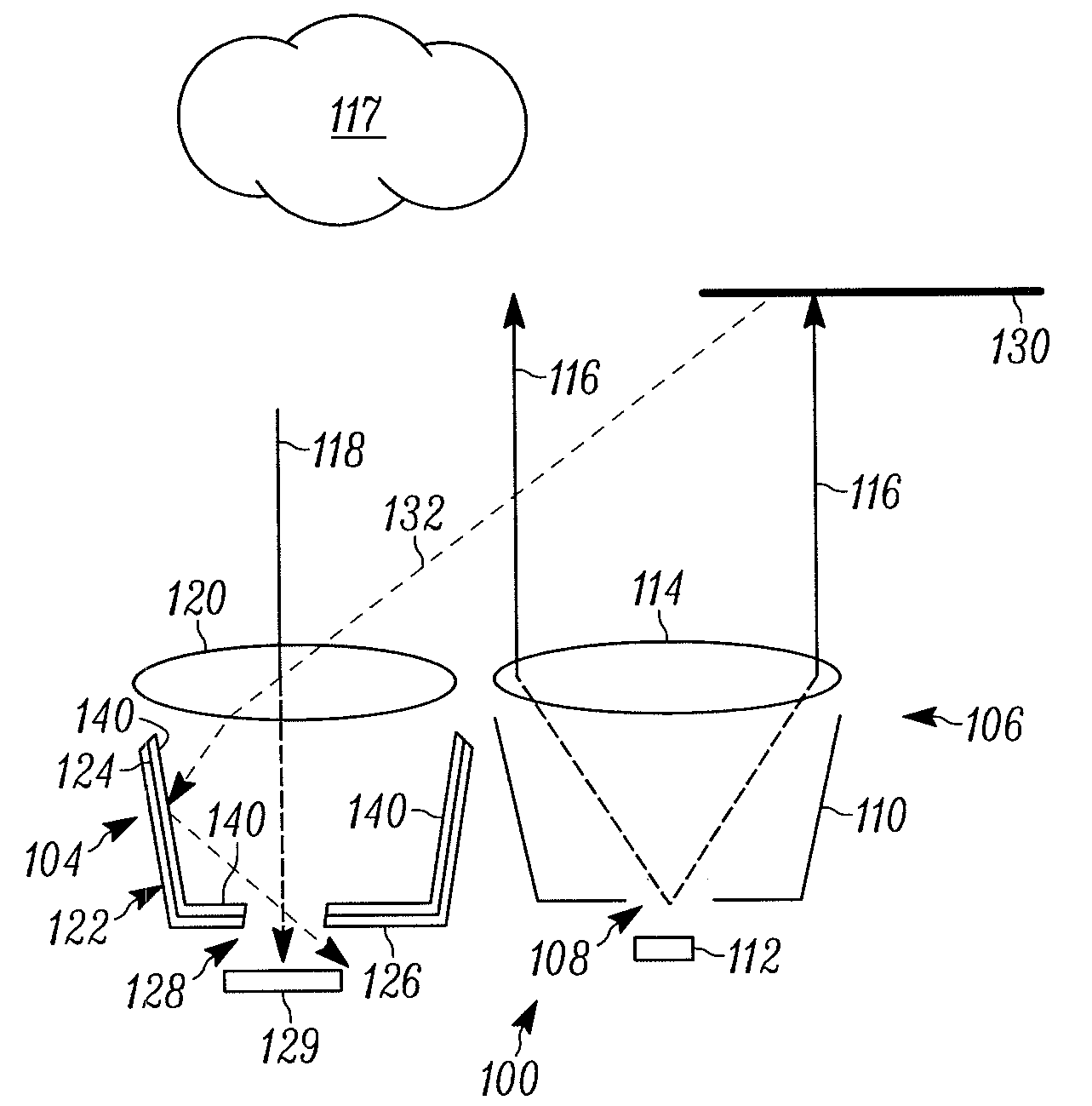
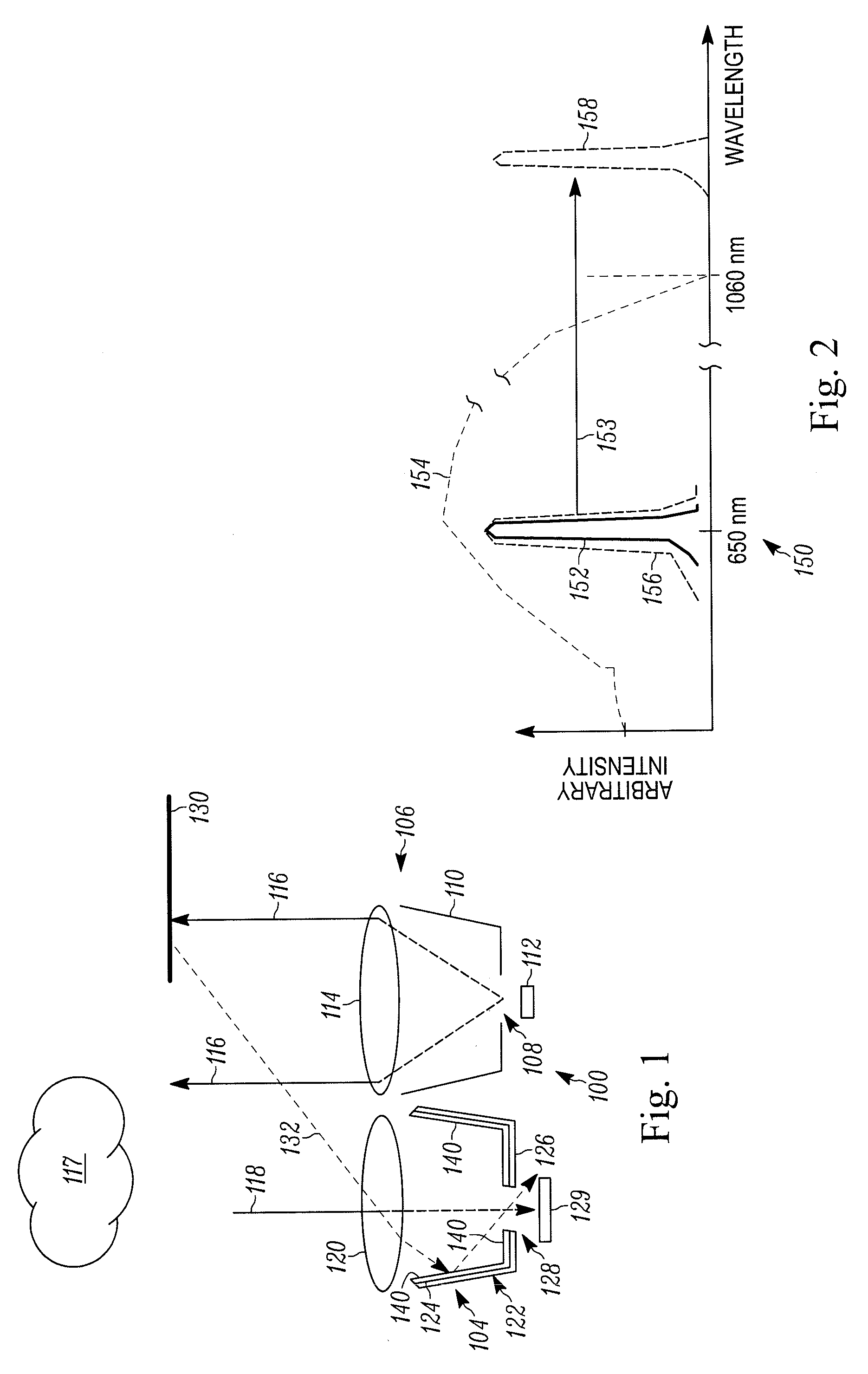
[0032]FIG. 1 shows in schematic form a cross-sectional side view of an exemplary optical or photoelectric sensor 100. It is to be understood that the sensor 100 as well as the other sensors discussed herein can include in some embodiments, one or more of numerous types of optical or photoelectric sensors including, for example, Through-Beam sensors (includes transmitter / receiver types, light curtain types) where the transmitter and receiver are in separate enclosures; Transceiver sensors (Reflective, Polarized Reflective, Diffuse, Background suppression types, Color sensors, Clear Object types, scanner types), Color Contrast sensors, and Time-Of-Flight sensors (through-beam types, transceiver types, and imaging types) where volumetric information is captured by the sensor opto-electronics circuits.

[0033]The sensor 100 shown in FIG. 1 particularly is depicted in operational relation to an exemplary target object 117 and a lambertian reflector 130. The sensor 100 includes a receiver 1...


PUM


Abstract

A variety of methods and systems are described that relate to reducing optical noise. In at least one embodiment, the method includes, emitting a first light having a selected wavelength from a light source, receiving a reflected first light onto a phosphor-based layer positioned inside a receiver, the reflected first light being at least some of the emitted first light that has been reflected by an object positioned outside of a desired target location. The method further includes, shifting the wavelength of the received reflected first light due to an interaction between the received reflected first light and the phosphor-based layer, and passing the received reflected first light with respect to which the wavelength has been shifted through a light detector without detection.

Description

CROSS-REFERENCE TO RELATED APPLICATIONS[0001]Not ApplicableSTATEMENT REGARDING FEDERALLY SPONSORED RESEARCH OR DEVELOPMENT[0002]Not ApplicableFIELD OF THE INVENTION[0003]The present invention relates to the field of optical sensing systems and methods and, more particularly, to systems and methods for optical noise reduction as can be employed in relation to such optical sensing systems and methods.BACKGROUND OF THE INVENTION[0004]Optical or photoelectric sensors use light to sense targets without physical contact and are used in a wide variety of applications and environments, such as to sequentially detect the presence or absence of targets on a conveyor belt. Various types of optical sensors are available, such as light curtains, transmitted beam sensors, retro-reflective sensors, and diffuse sensors. Typically, each of these sensors includes a light source, such as a light emitting diode (LED) or a laser, and a photodetector for detecting light, such as a photodiode or phototran...

Claims


Application Information

Patent Timeline
Patent Type & Authority Patents(United States)
IPC IPC(8): F21V9/16
CPCG01N21/01G01N21/255G01N2201/062G01N2201/0627
Inventor LEARD, FRANCIS L.
Owner ROCKWELL AUTOMATION TECH
Why Eureka
Try Eureka