
Method and apparatus for recovering indium from etching waste solution containing indium and ferric chloride

a technology of indium and ferric chloride, which is applied in the direction of moving filter element filters, filtration separation, separation processes, etc., can solve the problems of not recovering metals as valuables, increasing the amount of hydroxide generated as a whole, etc., and achieves the effect of increasing the total surface area of metals, improving recovery efficiency, and increasing ionization tendency

Inactive Publication Date: 2013-07-09
SHARP KK +1
View PDF13 Cites 0 Cited by
  • Summary
  • Abstract
  • Description
  • Claims
  • Application Information

AI Technical Summary

Benefits of technology

The present invention is a method for efficiently recovering indium from an etching waste solution. The method involves using a precipitation-inducing metal, such as zinc, which is made into a solid form and immersed in the etching waste solution containing indium and ferric chloride. The zinc acts as a precipitation-inducing metal and allows indium to precipitate on its surface. The precipitated indium is then detached and recovered. This method improves the recovery efficiency by utilizing the difference in ionization tendency between zinc and indium. The use of zinc as the precipitation-inducing metal increases the surface area of zinc for a metal precipitation reaction and enables easy recovery of the precipitated indium. The method is advantageous for recycling indium in the recycle process of liquid crystal televisions and other household electric appliances.

Problems solved by technology

However, ferric chloride is also precipitated as a hydroxide, resulting in the problem that the amount of sludges of hydroxides generated is increased as a whole.
Also, almost all sludges are put into iron-containing sludges, resulting in the problem that these metals are not recovered as valuables.

Method used


Image

  • Method and apparatus for recovering indium from etching waste solution containing indium and ferric chloride
  • Method and apparatus for recovering indium from etching waste solution containing indium and ferric chloride
  • Method and apparatus for recovering indium from etching waste solution containing indium and ferric chloride

Examples


embodiment 1

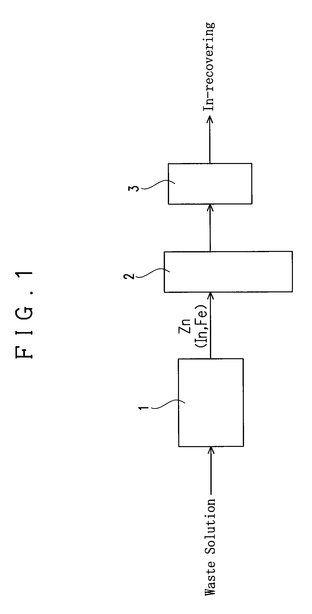
[0033]An apparatus of this embodiment for recovering indium (In) from an etching waste solution containing indium and ferric chloride is provided with a reaction vessel 1, a fluidizing apparatus and a filter 3 as shown in FIG. 1.

[0034]The reaction vessel 1 serves to receive an etching waste solution to immerse a precipitation-inducing metal in the etching waste solution and to allow to stand, thereby causing a reaction for precipitating In from the waste solution by the cementation reaction (metal precipitation reaction) based on a difference in ionization tendency between the precipitation-inducing metal and indium as explained later. A columnar one having a diameter of 3.5 mm and a length of 3.5 mm and including zinc (Zn) is used as the precipitation-inducing metal in this embodiment.

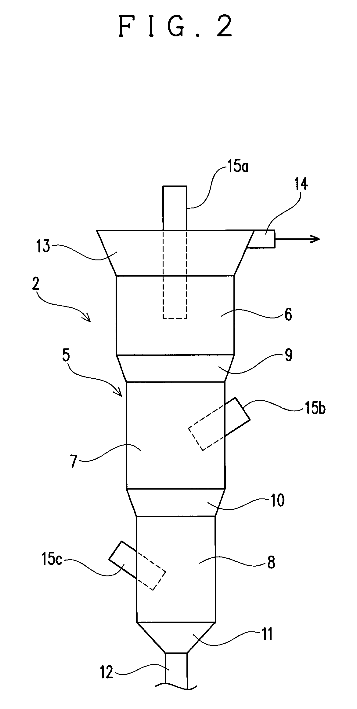
[0035]The fluidizing apparatus 2 serves to fluidize the precipitation-inducing metal with In precipitated thereon in a solution to detach the In precipitated on the precipitation-inducing metal. The f...

embodiment 2

[0056]This embodiment is different from the embodiment 1 in the structure of the apparatus body 5. Specifically, in this embodiment, an apparatus body 5, as shown in FIG. 3, has a structure in which the entire peripheral surface forms a taper spread upward, so that the sectional area of the apparatus body 5 is increased continuously with decrease in distance from the top of the apparatus body 5. This embodiment 2 is different in this point from the embodiment 1 in which the sectional area of the apparatus body 5 is discontinuously increased with decrease in distance from the top of the apparatus body 5. Since the apparatus body 5 of the this embodiment is structured such that it is not discontinuously but continuously increased in its sectional area, the apparatus body 5 of this embodiment is not divided into the apparatus upper part 6, the apparatus middle part 7 and the apparatus lower part 8 in its structure unlike the embodiment 1.

[0057]However, this embodiment is in common with...

embodiment 3

[0059]In this embodiment, as shown in FIG. 4, a dissolving vessel 4 is installed on the downstream side of the reaction vessel 1 and the upstream side of the fluidizing apparatus 2, and this embodiment differs in this point from the embodiment 1 provided with no dissolving vessel 4.

[0060]Specifically, in this embodiment, the precipitation-inducing metal which includes Zn and on which In and Fe have been precipitated in the reaction vessel 1 is not directly supplied to the fluidizing apparatus 2 to detach an alloy of In and Fe, but is supplied to the dissolving vessel 4 to dissolve In and Fe precipitated on the precipitation-inducing metal in the dissolving vessel 4. The dissolved In and Fe are again precipitated in the fluidizing apparatus 2. For this, the fluidizing apparatus 2 has not only a function of fluidizing the precipitation-inducing metal to detach an alloy of In and Fe but also a function as a reactor that precipitates In and Fe dissolved in the dissolving vessel 4, again...


PUM

PropertyMeasurementUnit
lengthaaaaaaaaaa
longitudinal lengthaaaaaaaaaa

Abstract

It is an object to provide a method and an apparatus for recovering indium, the method and apparatus ensuring that it is unnecessary to recover indium in the form of indium hydroxide, indium can be recovered easily by a filter or the like without handling inferiors and also, the recovery rate of indium is greatly improved. The method includes immersing a precipitation-inducing metal which includes zinc and is made into the form of a solid such that any part coming into view three-dimensionally has a longitudinal length of 2.5 to 10 mm in an etching waste solution containing at least indium and ferric chloride and allowed to stand, thereby allowing indium contained in the etching waste solution to precipitate on the surface of the precipitation-inducing metal based on a difference in ionization tendency between zinc and indium, and detaching the indium precipitated on the surface of the precipitation-inducing metal to recover it.

Description

TECHNICAL FIELD[0001]The present invention relates to a method and an apparatus for recovering indium from an etching waste solution containing indium and ferric chloride, and particularly, to a method and apparatus for recovering valuables, namely indium (In) in the form of an alloy, a metal simple substance or the like from an etching waste solution generated, for example, in the processes for manufacturing flat panel displays such as a liquid crystal display and plasma display.BACKGROUND ART[0002]Flat panel displays (FPD) such as liquid crystal displays and plasma displays are currently used for many of various electronic devices such as displays for display devices of computers or television image receiving devices and display parts of portable telephones. In a process for manufacturing such an FPD, it is needless to say that waste solutions are produced and it is necessary to treat these waste solutions. This is the same to not only to liquid crystal manufacturing factories whe...

Claims


Application Information

Patent Timeline
Patent Type & Authority Patents(United States)
IPC IPC(8): C22B3/44C22B58/00
CPCC22B3/46C22B7/006C22B58/00Y02P10/20C22B3/04C22B7/00
Inventor MIKI, TAKEOSUGIMOTO, TAMOTSUSAHASHI, EIICHIHONMA, TAKAMICHIMAESETO, TOMOHARU
Owner SHARP KK
Learn More