High efficiency solid state directional lighting including luminescent nanocrystal particles

a technology of luminescent nanocrystal particles and solid-state directional lighting, which is applied in the direction of discharge tube luminescnet screens, semiconductor devices for light sources, lighting and heating apparatus, etc. it can solve the problems of reducing the luminous insufficient phosphor conversion efficiency of conventional warm-white leds, and very energy-inefficient light sources. to achieve the effect of reducing heat transfer

Inactive Publication Date: 2013-08-13
LEDNOVATION
View PDF4 Cites 24 Cited by
  • Summary
  • Abstract
  • Description
  • Claims
  • Application Information

AI Technical Summary

Benefits of technology

[0012]The nano-particle size is sufficiently small to avoid divergence or scattering of the light waves, thereby overcoming the prior art problem of excessive light scattering caused by luminescent particles having sizes measured in microns.
[0013]The novel structure also spaces the nano-particles sufficiently apart from the semiconductor light source to reduce heat transfer from said light source to said particles, thereby overcoming the prior art problem associated with heat-induced phosphor degradation.

Problems solved by technology

It is well known that directional halogen lamps, like PAR lamps and MR lamps, or conventional ceiling spot lights, are very energy inefficient light sources; about 85-90% of the electricity they consume is released as heat rather than light.
However, conventional phosphor converted warm white LEDs have inadequate luminous efficacy due to multi-phosphors self-absorption loss, back-scattering loss of micro-particles and less human eye sensitivity of deep red light due to wide spectral width (full width of half maximum, FWHM) of reddish excitation light.
They also exhibit phosphor degradation due to high LED case temperature.
This conventional remote phosphor solution does not overcome the excessive light scattering problem due to its micro-particles size when used in directional lighting devices.

Method used


Image

  • High efficiency solid state directional lighting including luminescent nanocrystal particles
  • High efficiency solid state directional lighting including luminescent nanocrystal particles
  • High efficiency solid state directional lighting including luminescent nanocrystal particles

Examples


Embodiment Construction

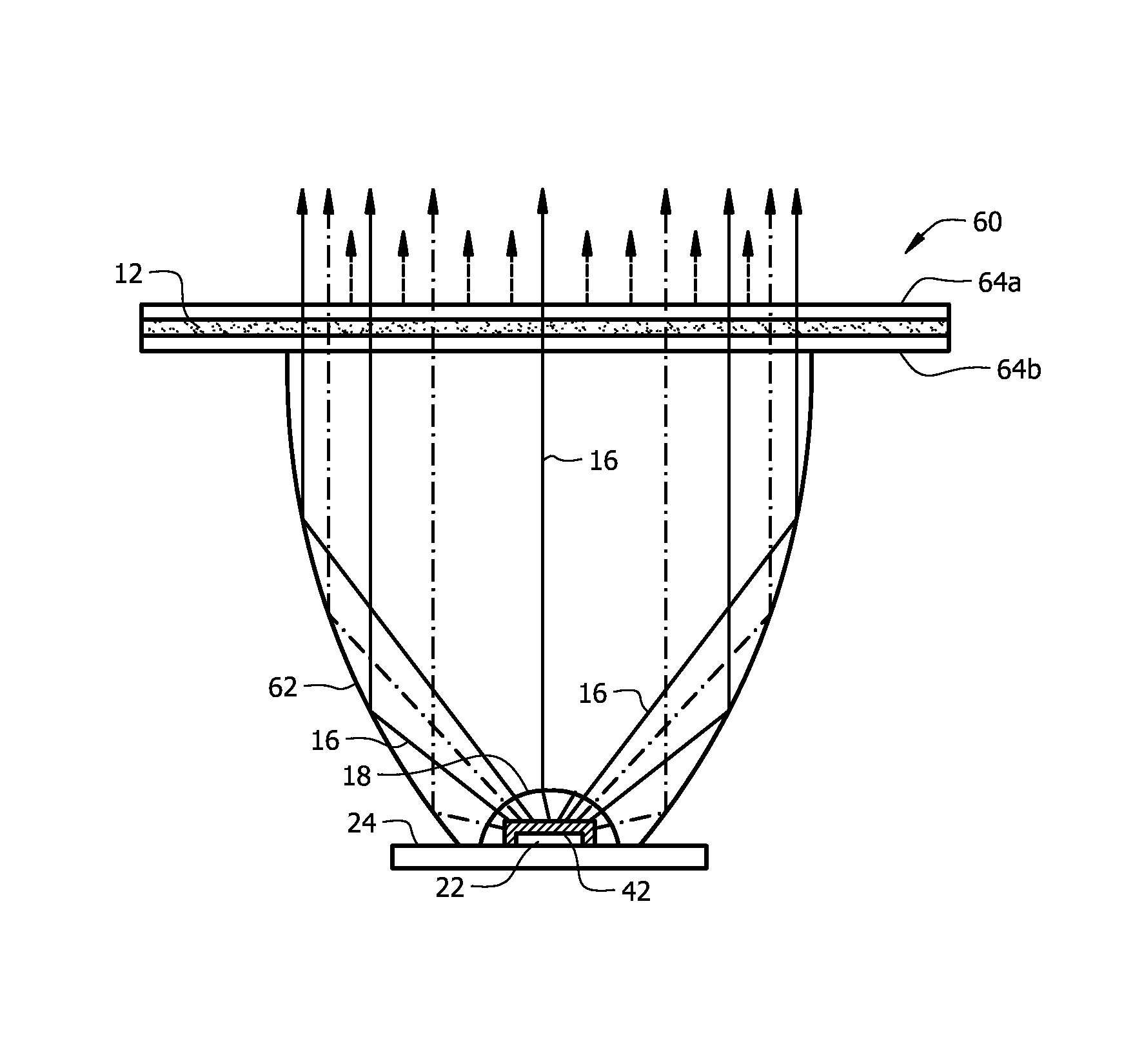
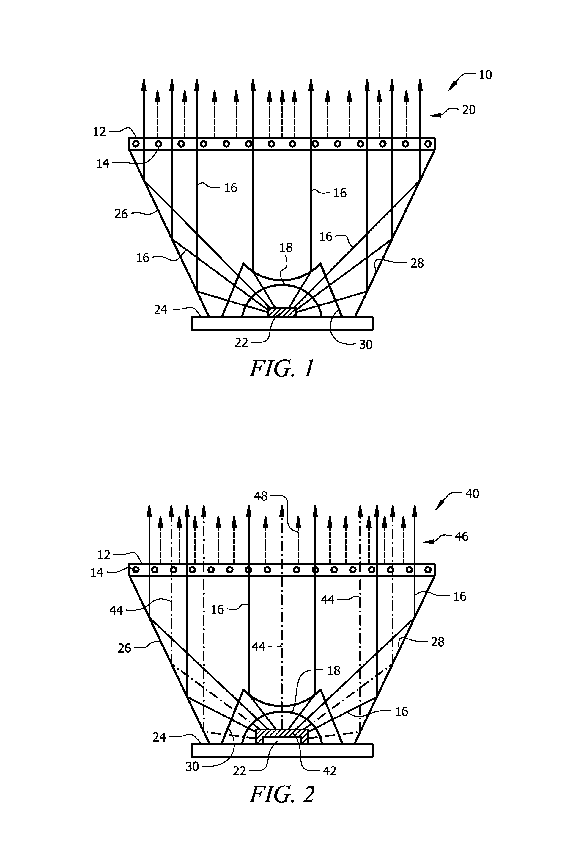
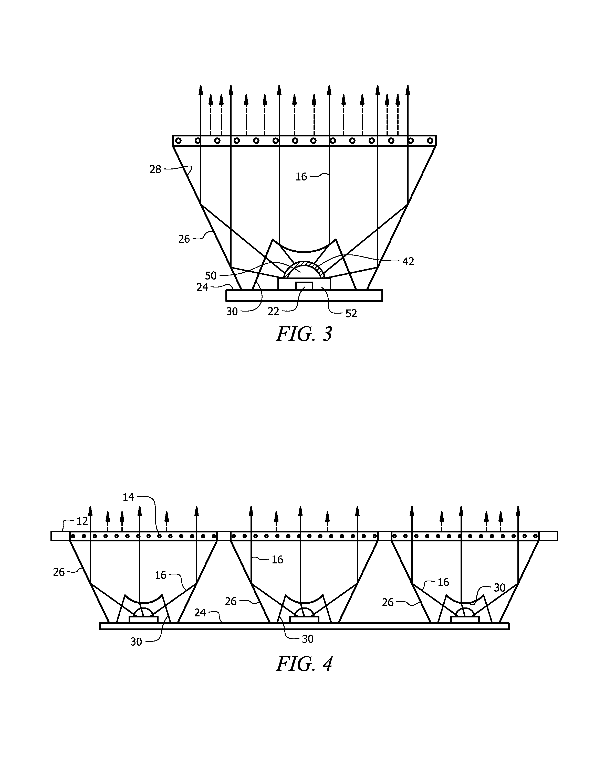
[0022]A first embodiment of the novel lighting device is denoted as a whole in FIG. 1 by the reference numeral 10.

[0023]Novel solid state directional lighting device 10 has a color conversion layer 12 including luminescent nanocrystal particles 14. At least a portion of collimated primary short wavelength light 16 from semiconductor light source 18 is converted into at least one long wavelength spectral light 20.

[0024]Semiconductor light source 18 includes at least one short wavelength semiconductor light emitting diode (LED) 22 mounted on printed circuit board 24. LED 22 emits a primary short wavelength light with peak wavelength of 380 nm-475 nm. Light from semiconductor light source 18 is reflected from frusto-conical sidewalls mounted about the periphery of said printed circuit board, said sidewalls forming a collimation lens 26 having a total internal reflection surface 28. Semiconductor light source 18 is positioned in cavity 30 as an entrance of said collimation lens.

[0025]Co...


PUM


Abstract

A solid state directional lighting device includes a semiconductor light source emitting a primary short wavelength light and a light collimation component disposed in light-reflecting relation to the light source to generate a collimated light with beam divergence angle less than forty degrees (40°). A luminescent nanocrystal conversion layer is disposed in the path of the collimated light and includes a luminescent nanocrystal conversion layer including luminescent nanocrystal particles with nano-particles sizes less than fifteen nanometers (15 nm). The luminescent nanocrystal particles absorb at least a portion of the collimated short wavelength light and convert the absorbed light into at least one long wavelength spectral light. A mixture of leakage primary short wavelength light and long wavelength light converted by the luminescent nano-particles produces a directional white light with luminous efficacy of at least one hundred lumens per Watt (100 lm / W). Light scattering is reduced due to the nano-particle size.

Description

BACKGROUND OF THE INVENTION[0001]1. Field of the Invention[0002]This invention relates to solid state lighting devices. More particularly, it relates to solid state directional lighting devices having high luminous efficacy with high color rendering index.[0003]2. Brief Description of the Related Art[0004]It is well known that directional halogen lamps, like PAR lamps and MR lamps, or conventional ceiling spot lights, are very energy inefficient light sources; about 85-90% of the electricity they consume is released as heat rather than light. Accordingly, efforts have been ongoing to develop solid state directional warm white lighting devices to replace these inefficient warm white halogen lamps and spot lights in a wide variety of applications. Moreover, where solid state lighting devices are already being used, efforts are ongoing to provide improvement with respect to energy efficiency, color rendering index, luminous efficacy (lm / W), color temperature, and duration of service, e...

Claims


Application Information

Patent Timeline
Patent Type & Authority Patents(United States)
IPC IPC(8): H05B33/00
CPCF21V9/16F21K9/56H01L33/507F21K9/137F21Y2101/02F21K9/233F21K9/64F21V5/10F21V9/32F21V9/38F21V13/14F21Y2115/10
Inventor MOREJON, ISRAEL J.ZHAI, JINHUI
Owner LEDNOVATION
Why Eureka
Try Eureka