Method for reducing formation of electrically resistive layer on ferritic stainless steels

a technology of ferritic stainless steel and resistive layer, which is applied in the direction of sustainable manufacturing/processing, heat treatment apparatus, final product manufacturing, etc., can solve the problems of brittle lacrosub>3 /sub>ceramic, difficult to fabricate, and liquid electrolytes, etc., to achieve the effect of reducing or eliminating

Active Publication Date: 2013-09-10
ATI PROPERTIES
View PDF9 Cites 0 Cited by
  • Summary
  • Abstract
  • Description
  • Claims
  • Application Information

AI Technical Summary

Benefits of technology

[0020]Another aspect of the present disclosure is directed a method of making a fuel cell interconnect. The method includes treating a silicon-containing ferritic stainless steel by subjecting the steel to oxidizing conditions under which silica including silicon derived from the steel forms on a surface of the steel. Optionally, at least a portion of the silica is removed from the surface. The treated steel is subsequently fabricated into the fuel cell interconnect. The method reduces the tendency for formation of an electrically resistive silica layer on the ferritic stainless steel interconnect when the interconnect is subjected to high temperature oxidizing conditions in service.
[0021]Yet another aspect of the present disclosure is directed to an article of manufacture comprising a ferritic stainless steel including at least a near-surface region that has been depleted of silicon relative to a remainder of the ferritic stainless steel. Such a characteristic reduces the tendency for the formation of an electrically resistive silica layer on a surface of the article when the article is subjected to high temperature oxidizing conditions. In certain non-limiting embodiments according to the present disclosure, a method according to the present disclosure is applied to the article in order to deplete (i.e., reduce or eliminate) silicon in a near-surface region of the steel. According to certain non-limiting embodiments, the article is a mill product (for example, a sheet, a plate, or a bar) or a fuel cell interconnect.

Problems solved by technology

Liquid electrolytes, however, typically are corrosive and can be difficult to handle.
LaCrO3 ceramic, however, is brittle, difficult to fabricate, and expensive.
A portion of the silicon added to the melt, however, unavoidably makes its way into the steel.
Therefore, even though silicon is intentionally added in such cases, it may be considered a residual impurity in the steel.
Silicon is detrimental to the operational efficiency of ferritic stainless steel interconnects since it tends to migrate to the steel surface / scale interface and form a thin, generally continuous, highly electrically resistive SiO2 (silica) layer at the interface.
This makes it increasingly difficult for electrons to pass through the interface region between the interconnect and the electrodes, and thereby progressively impairs the ability of the interconnects to conduct current between the cells.
This process, over time, can significantly reduce the overall efficiency of SOFCs including ferritic stainless steel interconnects.

Method used


Image

  • Method for reducing formation of electrically resistive layer on ferritic stainless steels
  • Method for reducing formation of electrically resistive layer on ferritic stainless steels
  • Method for reducing formation of electrically resistive layer on ferritic stainless steels

Examples


example 1

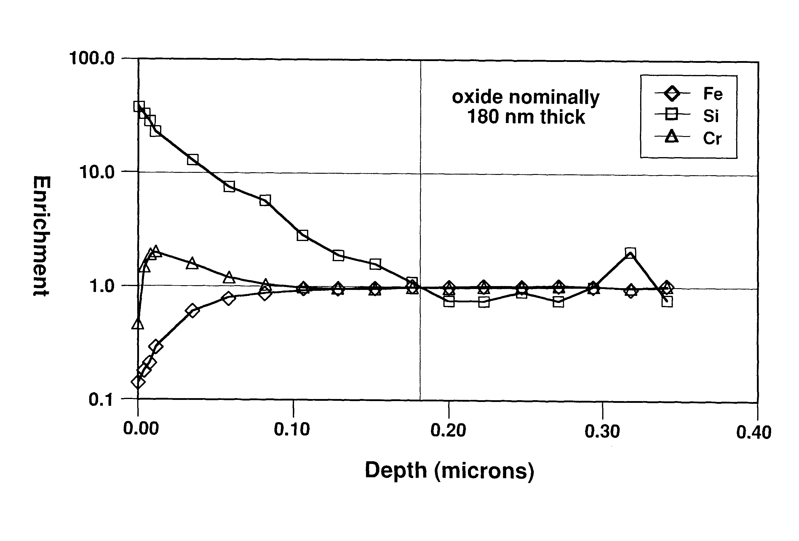
[0046]A 0.5 mm thick sample panel of AISI Type 430 stainless steel, which nominally includes 0.4 weight percent silicon, was annealed in a furnace chamber having a hydrogen atmosphere including a small concentration of water vapor, along with incidental impurities. The dew point of the hydrogen atmosphere was not measured but was believed to be in the range of about −20° C. to 0° C. The panel was heated in the furnace chamber at approximately 1010° C. for 30 minutes time-at-temperature (as measured by a contact thermocouple). The sample panel emerged from the furnace after heating with a dull surface tint, indicating that a relatively thick silica-containing layer (scale) had formed on the panel surface. The test panel was then examined using a scanning Auger microprobe having a depth profiling capability (via an ion sputtering gun). FIG. 3 illustrates the Auger compositional depth profile of the stainless steel sample, normalized to measure bulk composition. FIG. 3 plots relative e...

example 2

[0052]Several coupons of AISI Type 441 stainless steel having the alloy chemistry shown in Table 2 (shown in weight percentages) were prepared. Several of the coupons were heated at 1850° F. (1010° C.) in a mesh-belt furnace in a hydrogen atmosphere including a small concentration of water vapor. The water vapor concentration corresponded to a dew point of nominally −20° C. The coupons were within the heating zone of the furnace for approximately 30 minutes. The heat treatment produced a silica scale on the surface of the heated coupons, and these coupons are referred to in this example as the “pre-oxidized” samples. Other coupons of the same steel were not subjected to the heat treatment and are referred to in this example as “untreated” samples. It is known to form a homogenous single phase manganese cobaltite spinel (“MC”) coating on the surfaces of ferritic stainless steel SOFC interconnects to protect the fuel cells from chromium poisoning and to improve interconnect stability....

example 3

[0056]Coupons of the following ferritic stainless steels used in interconnect applications were prepared: AISI Type 430 (UNS S43000); Type 439 (UNS S43035); Type 441 (UNS S44100); and E-BRITE® alloy (UNS S44627). Coupons of Types 430, 439, and 441 were pre-oxidized to remove silicon from sub-surface regions of the coupons using the technique described above in Example 2 (i.e., 1010° C. for 30 minutes). Other coupons were left untreated. The coupons were then heated at 800° C. in simulated anode gas (SAG) for a time in excess of 1000 hours, and the normalized weight change (mg / cm2) of each sample was determined periodically. The SAG consisted of 4 vol. % hydrogen, 3 vol. % water vapor, and balance argon, and simulated the fuel side environment within a SOFC. The oxygen content within the SAG was low, but sufficient to oxidize the samples.

[0057]FIG. 6 is a plot of the test results. Pre-oxidation (i.e., desiliconization) was uniformly beneficial to the samples heated in the SAG. The re...


PUM

PropertyMeasurementUnit
partial pressureaaaaaaaaaa
weight percentaaaaaaaaaa
temperatureaaaaaaaaaa

Abstract

A method of reducing the formation of electrically resistive scale on a an article comprising a silicon-containing ferritic stainless subjected to oxidizing conditions in service includes, prior to placing the article in service, subjecting the article to conditions under which silica, which includes silicon derived from the steel, forms on a surface of the steel. Optionally, at least a portion of the silica is removed from the surface to placing the article in service. A ferritic stainless steel alloy having a reduced tendency to form silica on at least a surface thereof also is provided. The steel includes a near-surface region that has been depleted of silicon relative to a remainder of the steel.

Description

CROSS-REFERENCE TO RELATED APPLICATION[0001]The present application claims priority under 35 U.S.C. § 119(e) to U.S. Provisional Patent Application Ser. No. 60 / 905,219, filed Mar. 6, 2007.STATEMENT REGARDING FEDERALLY SPONSORED RESEARCH OR DEVELOPMENT[0002]Certain of the research leading to the present invention was funded by the United States government under Department of Energy Cooperative Agreement DE-FC26-05NT42513. The United States may have certain rights in the invention.BACKGROUND OF THE TECHNOLOGY[0003]1. Field of Technology[0004]The present disclosure relates to methods for limiting the formation of an electrically resistive surface layer or “scale” on stainless steels when the steels are subjected to high-temperature, oxidizing conditions. The present disclosure also relates to stainless steels and articles of manufacture including stainless steels, wherein the steels have a reduced tendency to form electrically resistive scale thereon when the steels are subjected to hi...

Claims


Application Information

Patent Timeline
Patent Type & Authority Patents(United States)
IPC IPC(8): C23C8/10H01M4/08
CPCC21D1/74C21D3/02C21D6/002C21D6/008C23C8/08H01M8/021H01B1/02C23C8/10H01M8/00H01M2008/1293Y02E60/50Y02E60/525H01M8/0228Y02P70/50C21D6/00C23C8/14
Inventor RAKOWSKI, JAMES M.
Owner ATI PROPERTIES
Why Eureka
Try Eureka