
Charged particle source from a photoionized cold atom beam

a charge particle and cold atom technology, applied in the direction of beam deviation/focusing, instruments, mass spectrometers, etc., can solve the problems of not addressing major problems, offering larger spot sizes or lower currents, and motis-based systems may have a maximum brightness, so as to reduce the cross-sectional area and reduce the velocity spread

Inactive Publication Date: 2013-09-10
US REPRESENTED BY THE SEC OF COMMERCE NIST
View PDF2 Cites 3 Cited by
  • Summary
  • Abstract
  • Description
  • Claims
  • Application Information

AI Technical Summary

Benefits of technology

This patent describes a system and method for producing a charged particle beam from a photoionized cold atom beam. The system includes an atomic vapor source and a beam formation subsystem with an aperture to selectively eliminate atoms with high velocities. The beam is then compressed along each transverse axis to reduce its cross-sectional area and velocity spread. The technical effect of this system is the production of a stable and high-quality charged particle beam with improved properties.

Problems solved by technology

However, FIBs which employ these LMIS sources may offer larger spot size or lower currents than may be desirable for such applications.
However, the MOTIS-based system may have a maximum brightness which is limited by diffusion of neutral atoms into the ionization volume.
They do not address major issues involved with efficiently converting an atom beam into a charged particle beam while achieving high beam brightness.
Cooling atoms to very low temperatures in convenient distances and ionizing atoms efficiently with available laser power may be problematic in beams with large axial velocities due to the small interaction times with the corresponding lasers.
Additionally, the coupling of energy between axial and transverse degrees of freedom in beams with a large axial velocity spread makes maintaining low transverse temperatures in the ion beam difficult.

Method used


Image

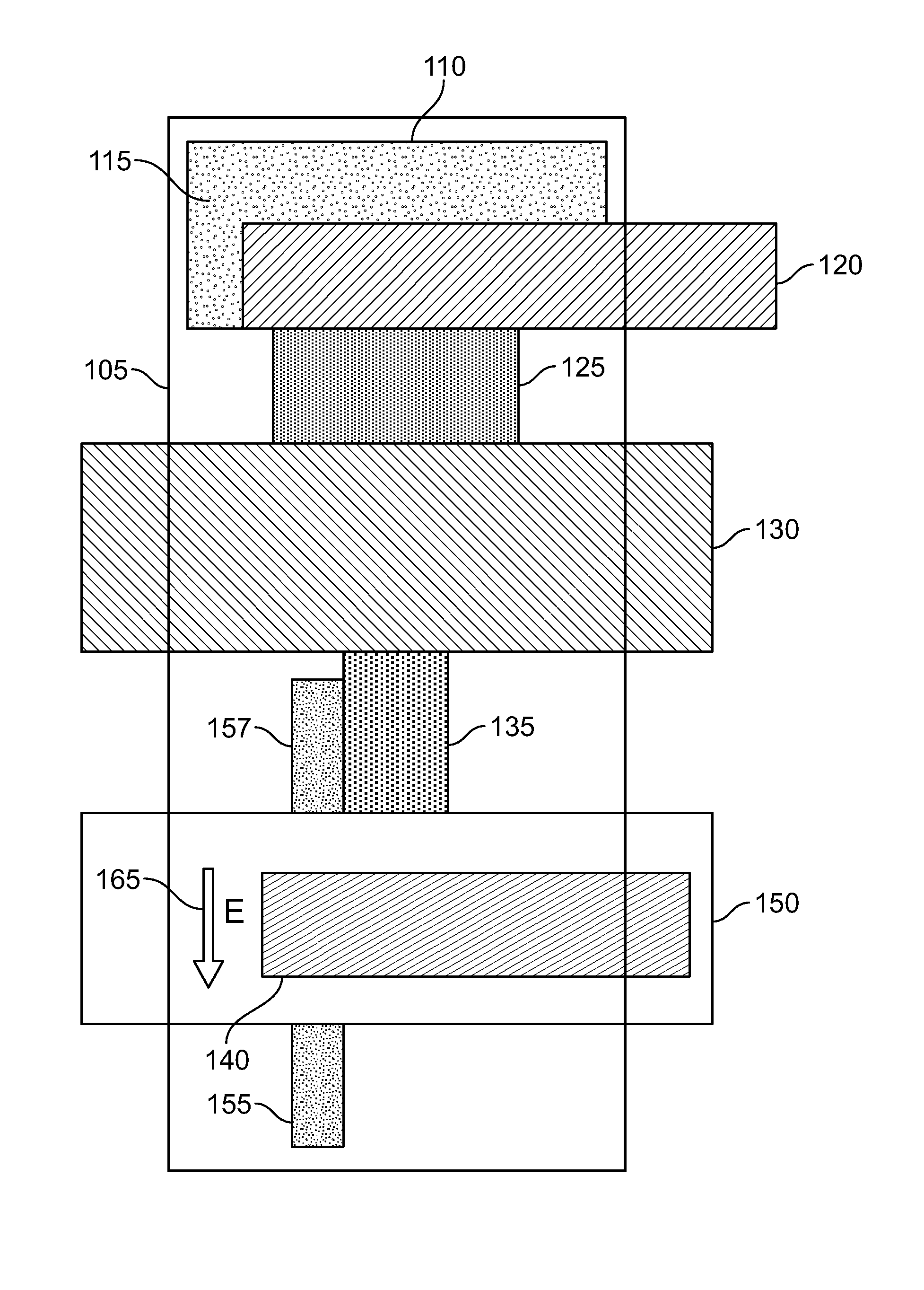
  • Charged particle source from a photoionized cold atom beam
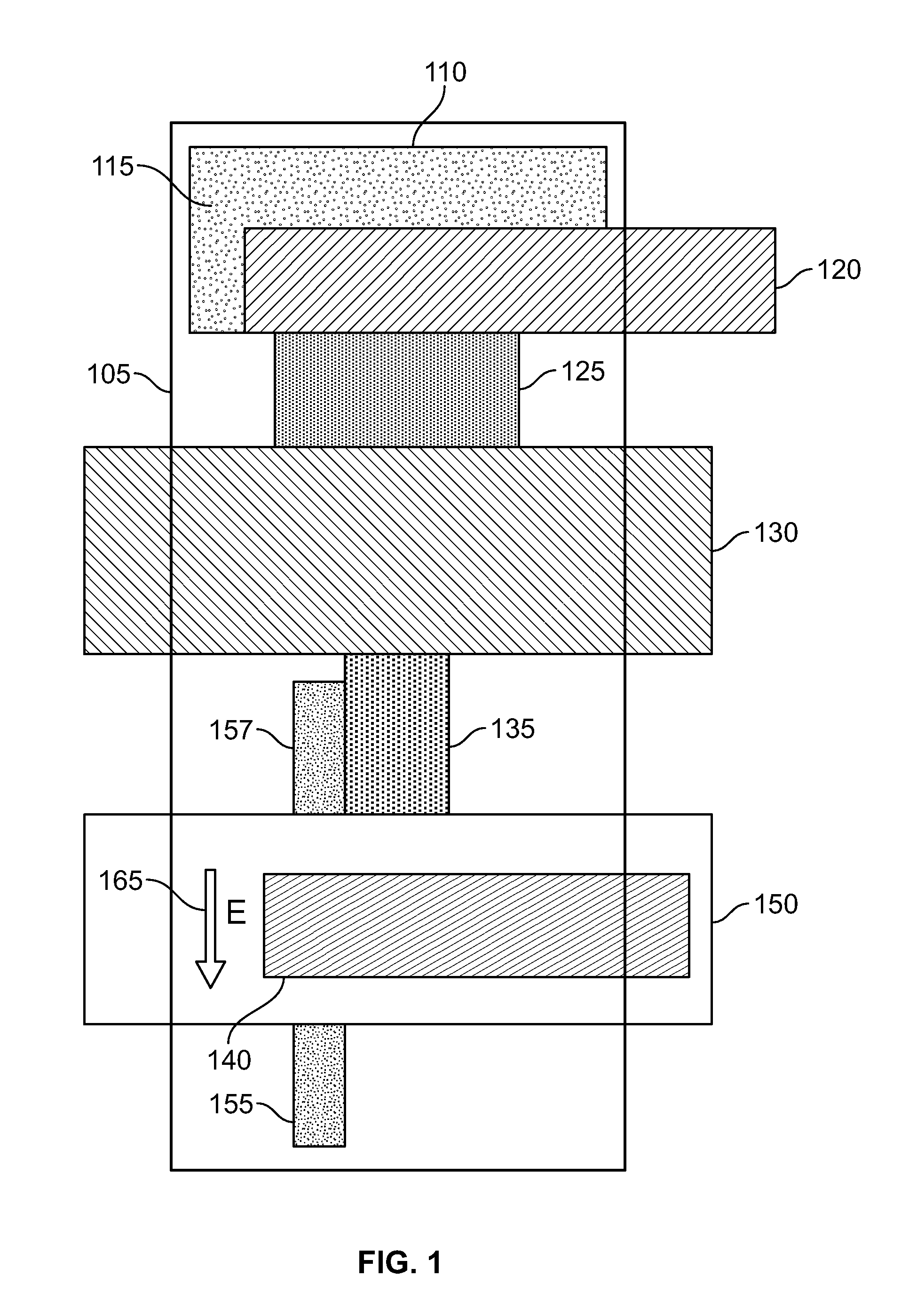
  • Charged particle source from a photoionized cold atom beam
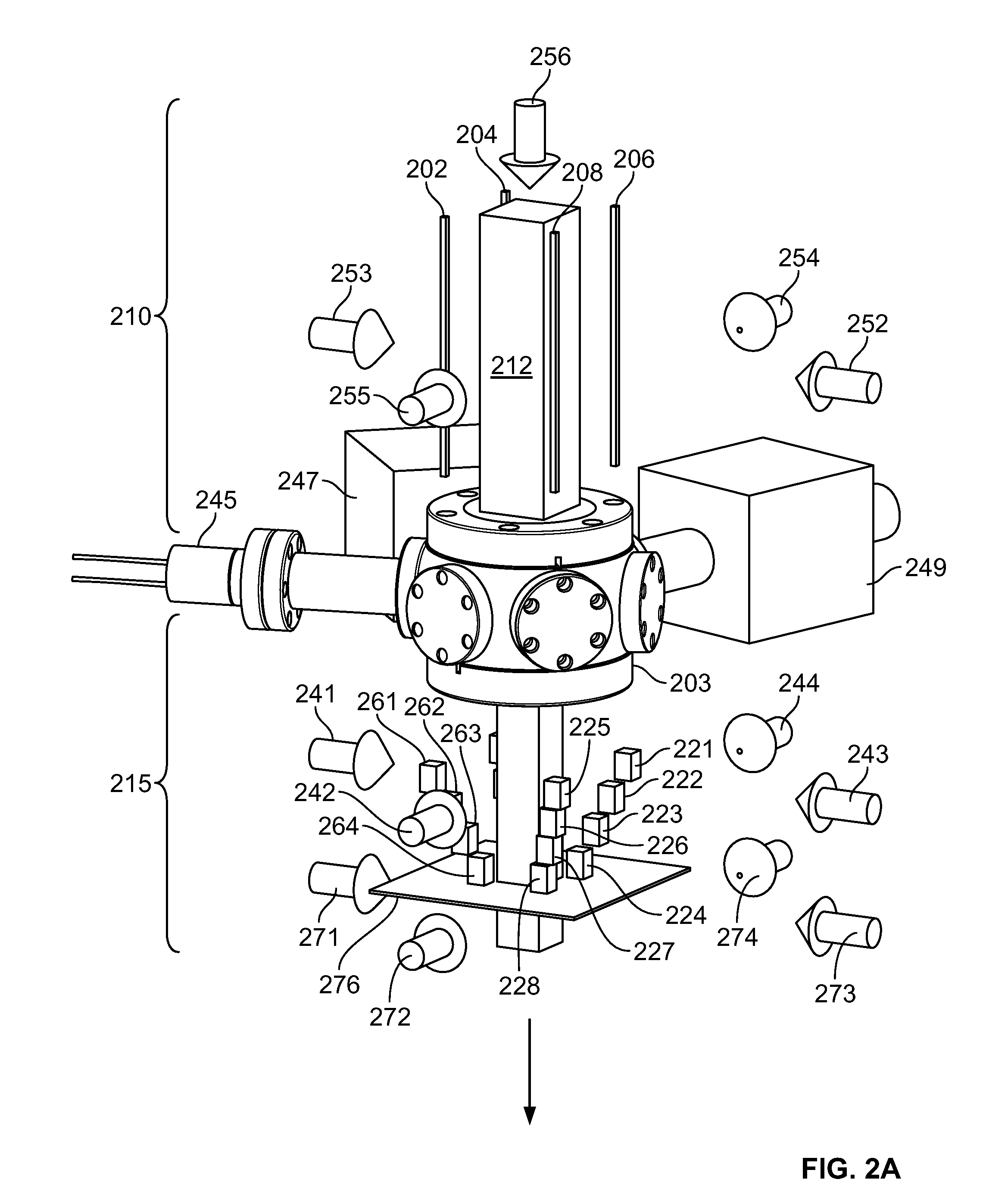
  • Charged particle source from a photoionized cold atom beam

Examples


Embodiment Construction

[0032]A system and method are described for creating a charged particle beam from a photoionized cold atom beam. The system and method may be used to create a low emittance, high brightness charged particle beam suitable for focusing to the nanoscale. The system and method may be compatible with any atomic species amenable to laser cooling. The system and method may be used to achieve a high ionization probability of the atom beam and suppression of the coupling between the axial spread velocity in the neutral beam and transverse velocity spread in the charged particle beam. The brightness of a charged particle beam produced by the system and method may depend on the neutral atom chosen.

[0033]In addition to the method for creating a charged particle beam from a photoionized cold atom beam, also described herein is a method for aligning an atom beam axis and electric field in an extraction system. This method may be useful in all systems in which a high brightness charged particle be...


PUM


Abstract

A system for producing a charged particle beam from a photoionized cold atom beam. A vapor of neutral atoms is generated. From these atoms, an atom beam having axial and transverse velocity distributions controlled by the application of laser light is produced. The produced atom beam is spatially compressed along each transverse axis, thus reducing the cross-sectional area of the produced beam and reducing a velocity spread of the produced beam along directions transverse to the beam's direction of propagation. Laser light is directed onto at least a portion of the neutral atoms in the atom beam, thereby producing ions and electrons. An electric field is generated at the location of the produced ions and electrons, thereby producing a beam of ions traveling in a first direction and electrons traveling in substantially the opposite direction. A vacuum chamber contains the atom beam, the ion beam and the electron beam.

Description

CROSS-REFERENCE TO RELATED APPLICATIONS[0001]The present application claims priority to provisional application Ser. No. 61 / 510,517, filed on or about Jul. 22, 2011, entitled “Cold Atom Beam Charged Particle Source” naming the same inventors as in the present application. The contents of this provisional application are incorporated by reference, the same as if fully set forth.STATEMENT REGARDING FEDERALLY SPONSORED RESEARCH / DEVELOPMENT[0002]The subject matter of this patent application was invented under the support of at least one United States Government contract. Accordingly, the United States Government may manufacture and use the invention for governmental purposes without the payment of any royalties.BACKGROUND OF THE INVENTION[0003]1. Field of Invention[0004]The present disclosure relates to charged particle sources and, more particularly, to a charged particle source created by photoionizing an atom beam of laser-cooled atoms in an electric field.[0005]2. Description of Rel...

Claims


Application Information

Patent Timeline
Patent Type & Authority Patents(United States)
IPC IPC(8): H01J27/24
CPCH01J27/24H01J37/065H01J37/08H05H3/02H01J27/022G21K1/00H01J2237/06333H01J2237/0815H01J2237/061
Inventor STEELE, ADAM V.KNUFFMAN, BRENTON J.MCCLELLAND, JABEZ J.
Owner US REPRESENTED BY THE SEC OF COMMERCE NIST
Learn More